On-Board Memory Interface
The on-board memory interface gives access to the memory resources available on the Euresys frame grabbers. It is based on AMBA® AXI4, an industry-standard protocol described in the AMBA® AXI and ACE Protocol Specification.

The on-board memory has 2 partitions: the
FIFO Buffer partition
This part of the on-board memory resources is dedicated to the frame grabber for the temporary storage of image data.
CustomLogic partition
This part of the on-board memory resources is dedicated to CustomLogic.
The following parameters provide the base address and the size of the CustomLogic partition:
| Signal | Width | Direction | Description |
|---|---|---|---|
| onboard_mem_base | 32 | Input |
Indicates the base address of the CustomLogic partition in the On-Board Memory |
| onboard_mem_size | 32 | Input |
Indicates the size in bytes of the CustomLogic partition in the On-Board Memory |
The partitions sizes are product-specific:
| Product | Memory partition size [Gigabytes] | |
|---|---|---|
| CustomLogic | FIFO Buffer | |
| 3602 Coaxlink Octo | 1 GB | 1 GB |
| 3603 Coaxlink Quad CXP-12 | 1 GB | 1 GB |
| 3603-4 Coaxlink Quad CXP-12 | 2 GB | 2 GB |
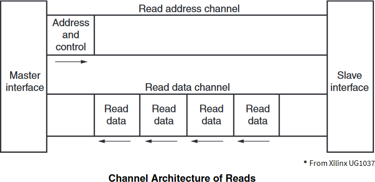
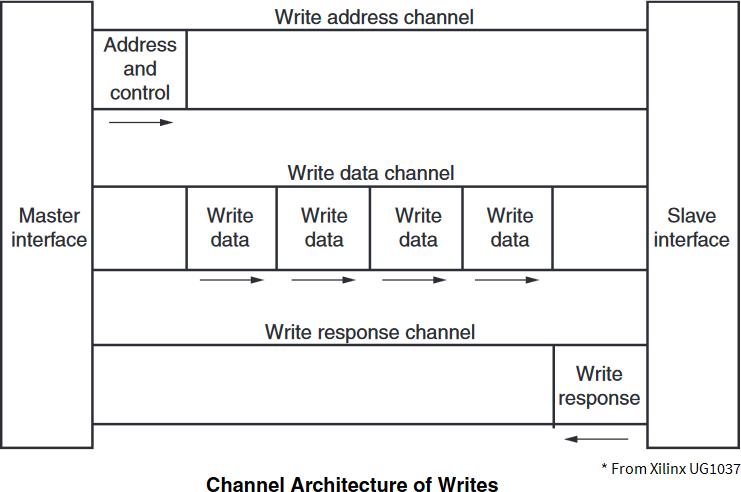
AMBA® AXI4 is a memory-mapped interface that consists of five channels:
| □ | Write Address Channel |
| □ | Write Data Channel |
| □ | Write Response Channel |
| □ | Read Address Channel |
| □ | Read Data Channel |
Data can move in both directions between the master and slave simultaneously, and data transfer sizes can vary. The limit in AMBA® AXI4 is a burst transaction of up to 256 data transfers.
The following sections briefly describe the AMBA® AXI4 signals.
For a complete view of signal, interface requirements and transaction attributes, please refer to AMBA® AXI and ACE Protocol Specification document at www.amba.com.
| Signal | Width | Direction | Description |
|---|---|---|---|
|
m_axi_resetn |
1 | Input |
RESETn resets the AMBA® AXI4 interface. |
| Signal | Width | Direction | Description | ||||||||||||
|---|---|---|---|---|---|---|---|---|---|---|---|---|---|---|---|
|
m_axi_awaddr |
32 |
Output |
Write address. The write address gives the address of the first transfer in a write burst transaction. |
||||||||||||
|
m_axi_awlen |
8 |
Output |
Burst length. The burst length gives the exact number of transfers in a burst. This information determines the number of data transfers associated with the address. Burst_Length = AWLEN[7:0] + 1 |
||||||||||||
|
m_axi_awsize |
3 |
Output |
Burst size. This signal indicates the size in bytes of each transfer in the burst. Burst_Size = 2^AWSIZE[2:0] |
||||||||||||
|
m_axi_awburst |
2 |
Output |
Burst type. The burst type and the size information, determine how the address for each transfer within the burst is calculated. Burst_Type: "00" = FIXED; "01" = INCR; "10" = WRAP |
||||||||||||
|
m_axi_awlock |
1 |
Output |
Lock type. Provides additional information about the atomic characteristics of the transfer. Atomic_Access: '0' Normal; '1' Exclusive |
||||||||||||
|
m_axi_awcache |
4 |
Output |
Memory type. This signal indicates how transactions are required to progress through a system. Memory_Attributes:
|
||||||||||||
|
m_axi_awprot |
3 |
Output |
Protection type. This signal indicates the privilege and security level of the transaction, and whether the transaction is a data access or an instruction access. Access_Permissions:
|
||||||||||||
|
m_axi_awqos |
4 |
Output |
Quality of Service, QoS. The QoS identifier sent for each write transaction. Quality_of_Service: Priority level |
||||||||||||
|
m_axi_awvalid |
1 |
Output |
Write address valid. This signal indicates that the channel is signaling valid write address and control information. |
||||||||||||
|
m_axi_awready |
1 |
Input |
Write address ready. This signal indicates that the slave is ready to accept an address and associated control signals. |
It is strongly recommended to set m_axi_awqos values below 8 to not disturb the other agents connected to the On-Board Memory.
The descriptions are excerpts from AMBA® AXI and ACE Protocol Specification.
| Signal | Width | Direction | Description |
|---|---|---|---|
|
m_axi_wdata |
W |
Output |
Write data. |
|
m_axi_wstrb |
W/8 |
Output |
Write strobes. This signal indicates which byte lanes hold valid data. There is one write strobe bit for each eight bits of the write data bus. |
|
m_axi_wlast |
1 |
Output |
Write last. This signal indicates the last transfer in a write burst. |
|
m_axi_wvalid |
1 |
Output |
Write valid. This signal indicates that valid write data and strobes are available. |
|
m_axi_wready |
1 |
Input |
Write ready. This signal indicates that the slave can accept the write data. |
In the Width column: "W" refers to MEMORY_DATA_WIDTH, the data width of the write data channel.
| ● | 3602 Coaxlink Octo |
| □ | (1-camera, custom-logic) => W = 128 ; |
| □ | (2-camera, line-scan, custom-logic) => W = 256; |
| ● | 3603 Coaxlink Quad CXP-12 and 3603-4 Coaxlink Quad CXP-12 |
| □ | (1-camera, custom-logic) => W = 256; |
| □ | (1-camera, line-scan, custom-logic) => W=256; |
| □ | (2-camera, custom-logic) => W = 256; |
| □ | (4-camera, custom-logic) => W = 256; |
The descriptions are excerpts from AMBA® AXI and ACE Protocol Specification.
| Signal | Width | Direction | Description | ||||||||||||
|---|---|---|---|---|---|---|---|---|---|---|---|---|---|---|---|
|
m_axi_bresp |
2 |
Input |
Write response. This signal indicates the status of the write transaction. Response:
|
||||||||||||
|
m_axi_bvalid |
1 |
Input |
Write response valid. This signal indicates that the channel is signaling a valid write response. |
||||||||||||
|
m_axi_bready |
1 |
Output |
Response ready. This signal indicates that the master can accept a write response. |
The descriptions are excerpts from AMBA® AXI and ACE Protocol Specification.
For m_axi_bresp:
| □ | OKAY: Normal access success. Indicates that a normal access has been successful. Can also indicate an exclusive access has failed. See OKAY, normal access success. |
| □ | EXOKAY: Exclusive access okay. Indicates that either the read or write portion of an exclusive access has been successful. |
| □ | SLVERR: Slave error. Used when the access has reached the slave successfully, but the slave wishes to return an error condition to the originating master. |
| □ | DECERR: Decode error. Generated, typically by an interconnect component, to indicate that there is no slave at the transaction address. |
| Signal | Width | Direction | Description | ||||||||||||
|---|---|---|---|---|---|---|---|---|---|---|---|---|---|---|---|
|
m_axi_araddr |
32 |
Output |
Read address. The read address gives the address of the first transfer in a read burst transaction. |
||||||||||||
|
m_axi_arlen |
8 |
Output |
Burst length. The burst length gives the exact number of transfers in a burst. This information determines the number of data transfers associated with the address. Burst_Length = ARLEN[7:0] + 1 |
||||||||||||
|
m_axi_arsize |
3 |
Output |
Burst size. This signal indicates the size in bytes of each transfer in the burst. Burst_Size = 2^ARSIZE[2:0] |
||||||||||||
|
m_axi_arburst |
2 |
Output |
Burst type. The burst type and the size information, determine how the address for each transfer within the burst is calculated. Burst_Type: "00" = FIXED; "01" = INCR; "10" = WRAP |
||||||||||||
|
m_axi_arlock |
1 |
Output |
Lock type. Provides additional information about the atomic characteristics of the transfer. Atomic_Access: '0' Normal; '1' Exclusive |
||||||||||||
|
m_axi_arcache |
4 |
Output |
Memory type. This signal indicates how transactions are required to progress through a system. Memory_Attributes:
|
||||||||||||
|
m_axi_arprot |
3 |
Output |
Protection type. This signal indicates the privilege and security level of the transaction, and whether the transaction is a data access or an instruction access. Access_Permissions:
|
||||||||||||
|
m_axi_arqos |
4 |
Output |
Quality of Service, QoS. The QoS identifier sent for each write transaction. Quality_of_Service: Priority level |
||||||||||||
|
m_axi_arvalid |
1 |
Output |
Read address valid. This signal indicates that the channel is signaling valid read address and control information. |
||||||||||||
|
m_axi_arready |
1 |
Input |
Read address ready. This signal indicates that the slave is ready to accept an address and associated control signals. |
It is strongly recommended to set m_axi_awqos values below 8 to not disturb the other agents connected to the On-Board Memory.
The descriptions are excerpts from AMBA® AXI and ACE Protocol Specification.
| Signal | Width | Direction | Description |
|---|---|---|---|
|
m_axi_rdata |
W |
Input |
Read data. |
|
m_axi_rresp |
2 |
Input |
Read response. This signal indicates the status of the read transfer. Response: "00" = OKAY; "01" = EXOKAY; "10" = SLVERR; “11” = DECERR |
|
m_axi_rlast |
1 |
Input |
Read last. This signal indicates the last transfer in a read burst. |
|
m_axi_rvalid |
1 |
Input |
Read valid. This signal indicates that the channel is signaling the required read data. |
|
m_axi_rready |
1 |
Output |
Read ready. This signal indicates that the master can accept the read data and response information. |
In the Width column: "W" refers to MEMORY_DATA_WIDTH, the data width of the write data channel.
| ● | 3602 Coaxlink Octo |
| □ | (1-camera, custom-logic) => W = 128 ; |
| □ | (2-camera, line-scan, custom-logic) => W = 256; |
| ● | 3603 Coaxlink Quad CXP-12 and 3603-4 Coaxlink Quad CXP-12 |
| □ | (1-camera, custom-logic) => W = 256; |
| □ | (1-camera, line-scan, custom-logic) => W=256; |
| □ | (2-camera, custom-logic) => W = 256; |
| □ | (4-camera, custom-logic) => W = 256; |
The descriptions are excerpts from AMBA® AXI and ACE Protocol Specification.

VALID/READY handshake timing diagram