The 3617 HD26F I/O Extension Module - TTL-CMOS5V accessory is an I/O extension module to be used with above listed frame grabber products.
This module adds a total of 24 I/O ports with a configurable mix of 2 types:
| □ | single-ended 5 V compliant TTL input |
| □ | single-ended 5 V CMOS output |
The module:
| □ | is powered by the frame grabber through the I/O EXTENSION cable. |
| □ | is software configurable. There are no jumpers. |
| □ | provides a persistent configuration. The last configuration is automatically restored at power-up |
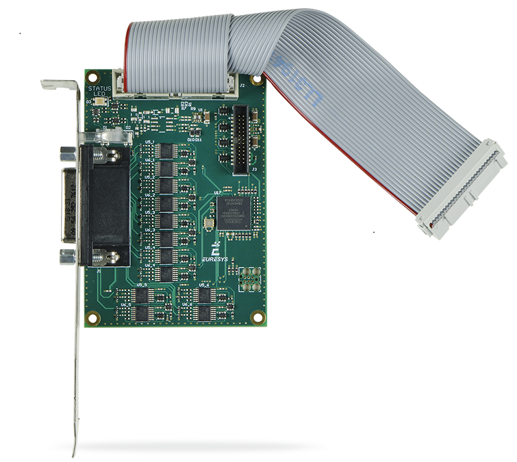
3617 HD26F I/O Extension Module - TTL-CMOS5V

This I/O extension module includes:
| □ | a PC bracket fitted with SubD connector and LED indicators. |
| □ | a printed circuit board assembly implementing the I/O drivers and receivers and a control logic. |
| □ | a 26-pin high-density flat cable for direct connection to the I/O extension connector of the compatible frame grabber. |
| ● | External I/O connector |
| □ | Robust 26-pin high-density Sub-D |
| □ | Compatible pin layout with External I/O connectors of compatible frame grabbers for 12 V/GND and signals pairs |
See also: HD26F 3617 External I/O Connector
| ● | Internal I/O connector |
| □ | Standard pitch 26-pin flat cable header |
| □ | Compatible pin layout with Internal I/O connectors of compatible frame grabbers for 12 V/GND and signals pairs |
See also: PHS26M 3617 Internal I/O Connector
| ● | I/O Extension connector |
| □ | Fine pitch 26-pin flat cable header fitted with the I/O Extension cable: a 150 mm length flat cable for direct connection to the I/O Extension connector of compatible frame grabbers |
See also: PHS26M-050 I/O Extension Connector
Activity LED #1 on bracket
The ACTIVITY LED #1 is dedicated to the activity of input ports
| LED State | Meaning |
|---|---|
| Green | Normal mode - Flashing indicates activity on at least one input. |
| Orange | Configuration mode |
| Red | Error - The I/O module is not (yet) controlled by the frame grabber |
| Off | The I/O module is not powered |
Activity LED #2 on bracket
The ACTIVITY LED #2 is dedicated to the activity of output ports
| LED State | Meaning |
|---|---|
| Green | Normal mode - Flashing indicates activity on at least one output. |
| Orange | Configuration mode |
| Red | Error - The I/O module is not (yet) controlled by the frame grabber |
| Off | The I/O module is not powered |
Status LED on board
The STATUS LED is dedicated to the activity of the I/O extension bus
| LED State | Meaning |
|---|---|
| Solid green | Normal mode - No activity on the bus. |
| Flashing green | Normal mode - Activity on the I/O extension bus. |
| Flashing orange | Configuration mode - Activity on the I/O extension bus. |
| Flashing red | Configuration mode - No activity on the I/O extension bus |
| Off | The I/O module is not powered |
| Specification Item | 3617 HD26F I/O Extension Module - TTL-CMOS5V | |
|---|---|---|
| Single-ended I/O | TTL Input/5 V CMOS Output | |
| Power output | Power Output Specifications | |
| Power consumption | < 5 W | |
| Group | Single-ended I/O | ||
|---|---|---|---|
| I/O# | Input | Output | |
| Group #1 | MIO1 MIO3 |
2 x TTL in | 2 x 5 V CMOS out |
| Group #2 | MIO5 MIO7 |
2 x TTL in | 2 x 5 V CMOS out |
| Group #3 | MIO9 MIO11 |
2 x TTL in | 2 x 5 V CMOS out |
| Group #4 | MIO13 MIO15 |
2 x TTL in | 2 x 5 V CMOS out |
| Group #5 | MIO17 MIO19 |
2 x TTL in | 2 x 5 V CMOS out |
| Group #6 | MIO21 MIO23 |
2 x TTL in | 2 x 5 V CMOS out |
| Group #7 | MIO25 MIO27 |
2 x TTL in | 2 x 5 V CMOS out |
| Group #8 | MIO29 MIO31 |
2 x TTL in | 2 x 5 V CMOS out |
| Group #9 | MIO33 MIO34 MIO35 MIO36 |
4 x TTL in | 4 x 5 V CMOS out |
| Group #10 | MIO37 MIO38 MIO39 MIO40 |
4 x TTL in | 4 x 5 V CMOS out |
The 24 I/O ports are configurable by group. There are 10 groups:
| □ | The groups #1 to #8 contain 2 single-ended I/O ports. |
| □ | The groups #9 and #10 contain 4 single-ended I/O ports. |
Within a group, it is allowed to set all the I/O ports:
| □ | for TTL input operation OR ... |
| □ | for 5 V CMOS output operation. |
The configuration is saved into a non-volatile memory on the I/O module. The configuration is automatically restored after applying power.
The IOExtensionModule category of the Interface module provides a set of features to configure the 3617 I/O extension module:
| □ | IOExtensionModuleConfiguration to enter/leave configuration mode |
| □ | IOExtensionModuleLineSelector to select a MIO to configure |
| □ | IOExtensionModuleLineFormat, IOExtensionModuleLineMode and IOExtensionModuleLineStatus to configure the selected MIO |
| □ | IOExtensionModuleLineToRepair and IOExtensionModuleErrorCount to help troubleshoot an invalid current configuration. |
Configuration procedure
| 1. | Select an Interface module |
| 2. | Enter the configuration mode: set IOExtensionModuleConfiguration to Begin |
| 3. | Select the I/O line to configure: set IOExtensionModuleLineSelector to the desired value (MIO1 to MIO40) |
| 4. | Select the single-ended I/O line format |
| □ | Set IOExtensionModuleLineFormat to TTL |
| 5. | Select the input or output I/O line mode: |
| □ | For an input, set IOExtensionModuleLineMode to Input |
| □ | For an output, set IOExtensionModuleLineMode to Output |
| 6. | Repeat from steps 3 for all I/O's to configure |
| 7. | Verify the validity of the configuration |
| □ | Get the value of IOExtensionModuleErrorCount |
| □ | If 0, the configuration is OK, proceed to next step |
| □ | If greater than 0, the configuration is NOK, proceed to step 10 |
| 8. | Record the configuration |
| □ | Set IOExtensionModuleConfiguration to Commit |
| □ | The procedure is complete! |
| 9. | Repair the configuration |
| □ | Get the value of IOExtensionModuleLineToRepair |
| □ | Read I/O configuration capabilities and constraints to determine why the indicated MIO doesn’t satisfy the configuration constraints. |
| □ | Adapt the configuration of one (or more) I/O's accordingly by proceeding from step 3 . |
The IOExtensionModuleInformation category of the Interface module provides information details.
| □ | IOExtensionModuleSerialNumber |
| □ | IOExtensionModulePartNumber |
| □ | OExtensionModuleProductCode |
| □ | IOExtensionModuleRevision |
| □ | IOExtensionModuleVariant |