Line Scan Acquisition Principles

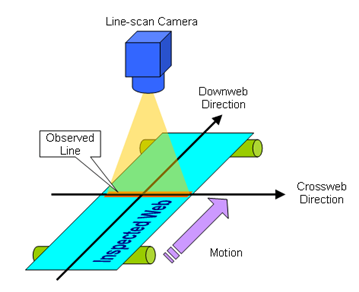
Typical line-scan imaging system
The expression “Line-scan imaging” designates machine vision applications where 2-D images are obtained by the combination of successive image lines captured from a 1-D imaging device that moves relatively to the object.
In line-scan imaging:
| ● | The imaging device is often, but not necessarily, a line-scan camera. |
| ● | The inspected object is often a continuous web, it can also be discrete objects having fixed or variable size. |
| ● | The inspected web moves relatively to the camera. The motion speed during the acquisition can be fixed or variable. |
| □ | The cross-web direction or transverse direction is the axis on the web plane that is observed by the camera. |
| □ | The down-web direction or axial direction is the motion direction of the inspected web relatively to the camera. |
Scanning area definitions
The scanning area is a 2-D area on the web having a width equal to FOV and a length equal to Scan Length.
In the cross-web direction (horizontal direction in the above drawing), the scanning area is delimited by the field of view – FOV – of the camera.
In the down-web direction (vertical direction in the above drawing), the scanning area is delimited by the start-of-scan and the end-of-scan positions. The line pitch is determined by the ratio between the web speed and the camera line rate.
The field of view – FOV – of a line-scan camera is determined only by the optical setup and the sensor geometrical properties.
The start-of-scan position is a position on the web corresponding to the scan-line boundary preceding the first acquired line.
The end-of-scan position is a position on the web corresponding to the scan-line boundary following the last acquired line.
Most of the line-scan cameras are delivering a single row of pixels every camera cycle. Consequently, multiple camera cycles are necessary to build-up the object image.
Unlike area-scan imaging, line-scan imaging allows the application to control the image pixel aspect ratio.
In the large majority of cases, the imaging application requires a constant, and preferably a 1:1 image pixel aspect ratio.
The cross-web pitch being locked by the sensor pitch and the optical magnification factor, the image pixel aspect ratio is controllable only through the line pitch control.
The following table summarizes the methods providing a constant line pitch that are applicable with Coaxlink:
| Method Name | Description |
|---|---|
| VCR |
Variable Camera cycle. The web speed is variable and the camera cycle rate is kept proportional to the web speed. The frame grabber builds the object image by capturing all the successive lines delivered by the camera. |
| CCC |
Constant Camera Cycle. The camera operates at a constant cycle rate and the frame grabber captures all the successive lines delivered by the camera. |
The VCR method requires:
| ● | A motion encoder for measuring the web speed. |
| ● | A real-time processing of the motion encoder events to build a camera trigger at a rate that is proportional to the motion encoder events rate. |
Having a proportional rate can be achieved by a divider tool or a multiplier/divider tool:
| ● | The divider tool decimates the input rate by an integer value, it delivers 1 out of N incoming events. |
| ● | The multiplier/divider tool enables fine control of the image pixel aspect ratio by allowing any rate conversion ratio value – RCR – in the range 0.001 to 1000 with an accuracy better than 0.1% of the RCR value. |
Image capture of small and large objects
For the transmission on the CoaXPress link, (most of) the line-scan cameras use one CoaXPress Image Data Stream.
Regarding the delivery methods of the image data, two cases are to be considered:
| ● | For small objects, the object image data are delivered into a single GenTL buffer. |
| ● | For big objects, the object image data are delivered into multiple GenTL buffers. |
In both cases, the image data are delivered through a single PCIe DMA channel and the transmission latency through Coaxlink is low: “one image line”.
In line-scan imaging, GenTL buffers are filled according to the following rules:
| ● | The first acquired line data of a scan is, by default, stored at the beginning of a new buffer. When vertical image flipping is enabled by setting StripeArrangement to Geometry_1X_1YE, the first acquired line data of a scan is stored at the location of the last full line of a new buffer. |
| ● | A buffer contains an integer number of image lines data. |
| ● | When the remaining space of a buffer is not sufficient to store an image line data, the acquisition continues into a new buffer and the filled buffer is made available to the application for processing. |
| ● | When the last line data of a scan is acquired, the last buffer, possibly partially filled, is made available to the application for processing. |
