
Connecting TTL Devices to Isolated Input Ports
Interfacing a device with a TTL or LVTTL output driver using a Coaxlink isolated input port
The isolated input ports of Coaxlink and Grablink products are, by design, compatible with TTL and LVTTL levels. No additional adapter is required to interconnect a (LV)TTL driver and an isolated input. The following section describes in detail how to connect them, what are the static voltage margins and what are the dynamic limitations.
Wiring Diagram
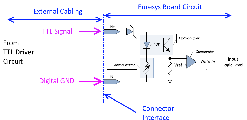
Connecting an (LV)TTL driver to an isolated input
Refer to Coaxlink I/O Connectors for I/O connectors pin assignments.
| 1. | Connect TTL Signal to IN+ |
| 2. | Connect TTL Circuit Ground (Digital GND) to IN- |
Important: As good practice, it is recommended to shield the whole set of wires, using a shielded cable.Shielding improve EMI protection against external interferences (immunity) and avoid unwanted EM emissions. The shield should be connected to the devices (PC, cameras, and systems components) chassis and should be separated from the digital GND line.
Static Levels Compatibility
|
(LV)TTL Driver |
(LV)TTL Driver |
Isolated-Input |
Voltage Margin |
Isolated Input |
|---|---|---|---|---|
|
Low |
0.4V max |
1.5V max |
1.1V |
Low |
|
High |
2.4V min |
1.9V min |
0.5V |
High |
The above table shows that the voltage levels are well compatible and that they remains acceptable voltage margins for both TTL and LVTTL applications.
Refer to Isolated Input for electrical specifications of isolated inputs.
Note: Note the circuit does not perform logic level inversion.
Note: The isolated input needs about 1 mA of current at high logic level. This is compatible with the current drive capabilities of (LV)TTL drivers at , as most (LV)TTL drivers provides +/-16 mA. Even old TTL technologies provides 4 mA min in any case.
Dynamic Limitations
Isolated inputs requires a minimum pulse high of 10 µs. The highest achievable pulse rate is 50 KHz.
Isolated inputs adds an extra delay of typically 5 µs (10 µs maximum).
Note: The delay can be sometimes ignored and sometimes not, according to the application.
For probably all the area-scan applications, such delay can be ignored, as is it very short compared to the camera cycle. For instance, such delay represents only 0.5 % of the cycle time of a super-fast 1,000 fps camera.For line-scan applications, the delay becomes significant since the camera cycle rate is much higher.