
Camera Link Cables
Cable Connectors
|
Designator |
Connector family |
Description |
|---|---|---|
|
MDR |
Mini Delta Ribbon |
1.27 mm-pitch blade 26-blade 2-row male plug |
|
SDR |
Shrunk Delta Ribbon |
0.8 mm-pitch blade 26-blade 2-row male plug |
Any combination of MDR and SDR connectors are valid.
Refer to Camera Link Interface for the required connector type at the frame grabber side.
Important: This Camera Link cable is built with 5 high-quality pairs dedicated to carry the signals of a single Channel Link. Consequently, this cable cannot be used as the second cable in Full and 80-bit configurations having two Channel Links.
Note: This Camera Link cable supports POCL and non-POCL cameras
Cable composition
|
Structure |
Impedance |
Suggested Gauge |
|
|---|---|---|---|
|
5 High-quality twisted pairs |
100 ohms differential |
AWG 28 (0.08 mm2à |
|
| 6 Twisted pairs | |||
|
4 wires |
N/A |
||
|
Overall shield |
80% coverage |
||
Wiring
|
Conductor |
Signal* |
Camera Pin# |
Frame Grabber Pin# |
Function* |
|---|---|---|---|---|
|
Shield |
SGND |
Shell clamp |
Shell clamp |
EMC shield |
|
HQ pair |
Xclk+ |
18 |
9 |
Channel Link clock (Pos) |
|
Xclk- |
5 |
22 |
Channel Link clock (Neg) |
|
|
HQ pair |
X0+ |
15 |
12 |
Channel Link data 0 (Pos) |
|
X0- |
2 |
25 |
Channel Link data 0 (Neg) |
|
|
HQ pair |
X1+ |
16 |
11 |
Channel Link data 1(Pos) |
|
X1- |
3 |
24 |
Channel Link data 1 (Neg) |
|
|
HQ pair |
X2+ |
17 |
10 |
Channel Link data 2 (Pos) |
|
X2- |
4 |
23 |
Channel Link data 2 (Neg) |
|
|
HQ pair |
X3+ |
19 |
8 |
Channel Link data 3 (Pos) |
|
X3- |
6 |
21 |
Channel Link data 3 (Neg) |
|
|
Pair |
CC1+ |
22 |
5 |
Camera Control 1 (Pos) |
|
CC1- |
9 |
18 |
Camera Control 1 (Neg) |
|
|
Pair |
CC2+ |
10 |
17 |
Camera Control 2 (Pos) |
|
CC2- |
23 |
4 |
Camera Control 2 (Neg) |
|
|
Pair |
CC3+ |
24 |
3 |
Camera Control 3 (Pos) |
|
CC3- |
11 |
16 |
Camera Control 3 (Neg) |
|
|
Pair |
CC4+ |
12 |
15 |
Camera Control 4 (Pos) |
|
CC4- |
25 |
2 |
Camera Control 4 (Neg) |
|
|
Pair |
SerTC+ |
7 |
20 |
Serial to Camera (Pos) |
|
SerTC- |
20 |
7 |
Serial to Camera (Neg) |
|
|
Pair |
SerTFG+ |
21 |
6 |
Serial to Grabber (Pos) |
|
SerTFG- |
8 |
19 |
Serial to Grabber (Neg) |
|
|
Wire |
Power |
1 |
1 |
Power (nominal 12V DC) |
|
Wire |
GND |
14 |
14 |
Power Return |
|
Wire |
GND |
13 |
13 |
Power Return |
|
Wire |
Power |
26 |
26 |
Power (nominal 12V DC) |
Note: (*)The signal and function columns correspond to the cable used in a Base configuration and the first cable of a Medium configuration.
Note: This wiring does not implement a straightforward pin-to-pin connection. However, the pin assignment is such that the cable can be installed in any direction.
Important: Twisted pairs and wires should imperatively be individually shielded.
Layout
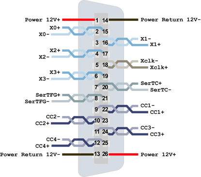
Camera Link PoCL connector (cable side of the connector connected to the camera)
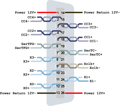
Camera Link PoCL connector (cable side of the connector connected to the board)
Note: This Camera Link cable is built with 10 high-quality pairs dedicated to carry the signals of two Channel Links. This cable is universal, it can be used not only as the second cable in Full and 80-bit configurations having two Channel Links but also as the first and second cable in any configuration.
Note: This Camera Link cable supports POCL and non-POCL cameras
Cable composition
|
Structure |
Impedance |
Suggested Gauge |
|
|---|---|---|---|
|
10 High-quality twisted pairs |
100 ohms differential |
AWG 28 (0.08 mm2à |
|
| 1 Twisted pair | |||
|
4 wires |
N/A |
||
|
Overall shield |
80% coverage |
||
Wiring
| Conductor |
Signal* |
Camera |
Frame |
Function* |
|---|---|---|---|---|
| Shield |
SGND |
Shell clamp |
Shell clamp |
EMC shield |
| HQ pair |
Yclk+ |
18 |
9 |
Channel Link Y clock (Pos) |
|
Yclk- |
5 |
22 |
Channel Link Y clock (Neg) |
|
| HQ pair |
Y0+ |
15 |
12 |
Channel Link Y data 0 (Pos) |
|
Y0- |
2 |
25 |
Channel Link Y data 0 (Neg) |
|
| HQ pair |
Y1+ |
16 |
11 |
Channel Link Y data 1(Pos) |
|
Y1- |
3 |
24 |
Channel Link Y data 1 (Neg) |
|
| HQ pair |
Y2+ |
17 |
10 |
Channel Link Y data 2 (Pos) |
|
Y2- |
4 |
23 |
Channel Link Y data 2 (Neg) |
|
| HQ pair |
Y3+ |
19 |
8 |
Channel Link Y data 3 (Pos) |
|
Y3- |
6 |
21 |
Channel Link Y data 3 (Neg) |
|
| HQ pair |
Zclk+ |
24 |
3 |
Channel Link Z clock (Pos) |
|
Zclk- |
11 |
16 |
Channel Link Z clock (Neg) |
|
| HQ pair |
Z0+ |
21 |
6 |
Channel Link Z data 0(Pos) |
|
Z0- |
8 |
19 |
Channel Link Z data 0 (Neg) |
|
| HQ pair |
Z1+ |
22 |
5 |
Channel Link Z data 1(Pos) |
|
Z1- |
9 |
18 |
Channel Link Z data 1 (Neg) |
|
| HQ pair |
Z2+ |
23 |
4 |
Channel Link Z data 2 (Pos) |
|
Z2- |
10 |
17 |
Channel Link Z data 2 (Neg) |
|
| HQ pair |
Z3+ |
25 |
2 |
Channel Link Z data 3 (Pos) |
|
Z3- |
12 |
15 |
Channel Link Z data 3 (Neg) | |
| Pair |
TERM |
7 |
20 |
|
|
TERM |
20 |
7 |
||
| Wire |
Power |
1 |
1 |
Power (nominal 12V DC) |
| Wire |
GND |
14 |
14 |
Power Return |
| Wire |
GND |
13 |
13 |
Power Return |
| Wire |
Power |
26 |
26 |
Power (nominal 12V DC) |
Note: (*)The signal and function columns correspond to the second cable used in Full and 80-bit configurations.
Note: This wiring does not implement a straightforward pin-to-pin connection. However, the pin assignment is such that the cable can be installed in any direction.
Important: Twisted pairs and wires should imperatively be individually shielded.