Easy3D calibration is a powerful process that uses a single scan of a calibration object to calibrate a laser triangulation setup.
| 1. | The calibration process generates a calibration model. |
| 2. | Easy3D uses this calibration model to transform the laser profile scans (or depth maps) into metric, distortion free point clouds. |
| ● | The calibration model includes all the geometric parameters required for this transformation: |
| □ | The relative position of the laser and the camera. |
| □ | The projection and the distortion model of the camera. |
| □ | The relative motion of the object. |
This document explains all the steps involved in the calibration process, from the design of the calibration object to the Open eVision API.
The calibration object
The general principle of Easy3D calibration is to match a scan of a known calibration object to its true geometric dimensions.
The double pyramid
In Open eVision 2.7 the “double truncated pyramid” calibration object is recommended over the "double pyramid" model.
The dimensions of the “double pyramid” calibration object along the X-, Y- and Z-axes are named A, B and C respectively.
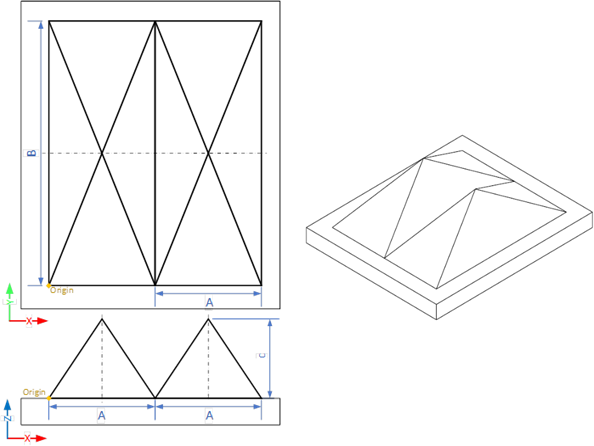
The "double pyramid" calibration model
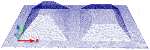
The truncated double pyramid
| ● | The dimensions of the “double truncated pyramid” calibration object the X-, Y- and Z-axes are named A, B and C respectively. |
| ● | The design of the double truncated pyramid must follow the ratios given in the illustration below. |
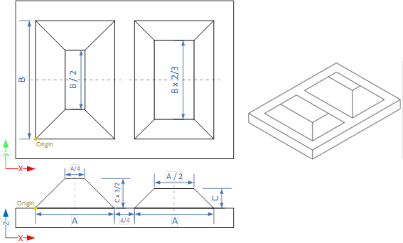
The "double truncated pyramid" calibration model (recommended)
| ● | For example, the provided CAD files of the calibration object use A = 4 cm, B = 6 cm and C = 1 cm. The Calibration Object Size, required for the calibration process, are the values A, B and C. |
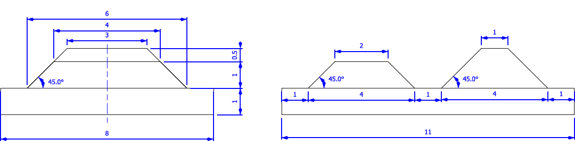
The "double truncated pyramid" calibration model with A = 4, B = 6 and C = 1
Building a calibration object
Overall dimensions
| ● | Manufacture a calibration object that fits the working area of the project. |
| ● | For example, if the project targets the inspection of a PCB (a printed circuit board as illustrated), design your calibration object with: |
| a. | The dimension A or B (it does not matter) similar to the width of the PCB. |
| b. | The height (C) of only several millimeters. |
This is not a strict requirement, if the scanned object is slightly larger or smaller than the calibration object, the calibration process is still valid.
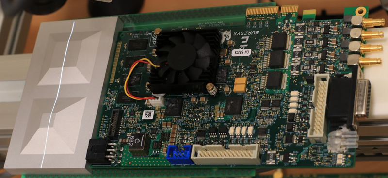
A PCB scanning setup with the associated calibration object
The calibration object dimensions (A, B and C) match the width and the height of the PCB
There is no constraint on the orientation of the calibration object during the scan:
- The X-axis can be aligned with the motion direction or with the laser line.
- After the calibration process, the origin and axes of the 3D calibrated point cloud follow the conventions of the reference design.
A calibrated point cloud with the origin and the axis of the coordinates system
The 3D origin is located at the external corner of the higher pyramid
Precision and tolerance
The relevant dimensions of the calibration object are the width, the length and the height of the pyramids (called A, B and C in the illustrations).
| □ | The relative dimensions to A, B and C (B/2, A/4…) are important and you must execute them with the same precision. |
| □ | The dimensional tolerances are related to the overall expected precision. |
If you want to achieve measurements on the point cloud with a precision of 0.01 mm, the manufacturing of the calibration object must have the same precision.
| □ | These tolerances only apply to the pyramids geometry, the calibration process does not use the dimensions of the support. |
| □ | The planar surfaces must be flat between 2 parallel planes separated by the target tolerance, as illustrated. |
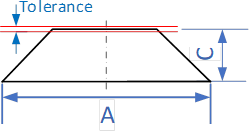
The tolerance of the pyramids sides is defined as the smallest distance between two parallel planes that contain the entire surface
Material and surface finishing
The goal is to obtain the laser profile as thinnest as possible over the whole object surface with the largest reflected energy.
The build material and the surface finishing are also important and must have:
| □ | A good reflectance, with diffuse reflection (no specular reflections). |
| □ | No transmission and limited diffusion inside the material. |
You can obtain a good surface finishing using aluminum material and blasting. Blasting gives the surfaces a satin gray finish.
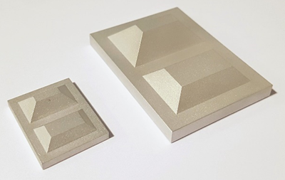
2 aluminum machined calibration objects with a micro-abrasive blasting surface treatment
3D CAD models
The calibration object models are available in various 3D CAD format like STEP, OBJ and STL.
Download these files from the Open eVision download area in the Additional Resources section (www.euresys.com/Support).
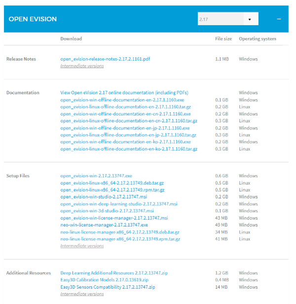
Download the calibration object models
Scanning the calibration object
| ● | The scan of the calibration object produces a depth map. |
| ● | To ensure a correct detection of the calibration object and a precise calibration model, you must fulfill the following criteria: |
| □ | All faces of the calibration object must be visible on the depth map (this affects the orientation of both the camera and the laser). |
| □ | No other object can be higher than the calibration object in the depth map. |
| □ | The depth map must have at least 200 x 200 pixels. |
| □ | The calibration object must cover at least 50% of the defined pixels of the depth map. |
| ● | Examples of bad scans: |
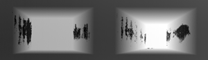
Missing pixels on the side faces

Not enough lines
The calibration object is too small on the depth map
Calibration with Easy3D Studio
Easy3D Studio is a free application that helps you to set up a laser triangulation scanner. You can easily set the acquisition parameters of the Coaxlink Quad 3D LLE frame grabber and perform the calibration.
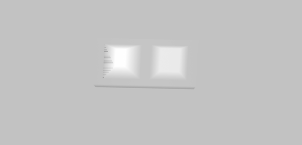
The DepthMap panel
This panel displays:
| □ | The scanned image. |
| □ | The acquisition parameters on the right side. |

The PointCloud panel
This panel displays:
| □ | The depth map of the scanned image. |
| □ | The object-based calibration parameters on the right side. |
| □ | The Calibrate button computes the calibration model using the last scanned depth map. |
| □ | When the calibration model is ready, the depth map is transformed into a point cloud. |
| □ | You can export the calibration model for later use. |

Required parameters
The calibration based on a calibration object requires several parameters:
| ● | Set the Object Type as DoublePyramid or TruncatedDoublePyramid. |
| □ | The DoublePyramid object type is deprecated and not recommended. |
| ● | Set the Object Size to represent the real size of the calibration object. |
| □ | If your calibration object has a base of 20 mm by 30 mm and a height of 5 mm, set these values in the Object Size A/B/C parameters. |
| □ | The point cloud after the calibration uses coordinates in millimeters. |
| ● | Set the parameter Precision Vs Speed Trade Off to define the time spent on the calibration process. |
| □ | The 3 possible values are Fast, Balanced and Precise. |
| ● | Set the parameter Passes count to define the number of iterations used to refine the calibration model. |
| □ | Use 1 for the fastest processing. |
| □ | Use up to 3 for slower but potentially better calibration model. |
Using the calibration with Open eVision
| ● | The class EObjectBasedCalibrationModel is the container for the object based calibration model. |
| ● | The class EObjectBasedCalibrationGenerator performs the computation of such a model using an EDepthMap8/16/32f as input. |
The following code snippet illustrates the calculation of a calibration model:
                    // Initialize a depth map from an image of a double truncated pyramid

                    EDepthMap16 depth_map;
depth_map.LoadImage("ctx1 calibration object.png");	// from Easy3D sample images
depth_map.SetZResolution(1.f / (1 << 5));		// 11.5 fixed point pixel format

// Initialize the calibration generator
EObjectBasedCalibrationGenerator calib_generator;
calib_generator.SetCalibrationObjectType(EObjectBasedCalibrationType_TruncatedDoublePyramid, 40.f, 60.f, 10.f); // Type and size of the calibration object

// Compute the calibration modelEObjectBasedCalibrationModel calib_model;
calib_model = calib_generator.Compute(depth_map);
float error = calib_model.GetCalibrationError();

// Save the calibration model
calib_model.Save("calib.model");.
                    // Initialize a depth map from an image of a double truncated pyramid
EDepthMap16 depth_map = new EDepthMap16();
depth_map.LoadImage("ctx1 calibration object.png"); // from Easy3D sample images
depth_map.ZResolution = 1.0F / 32.0F; // 11.5 fixed point pixel

// Initialize the calibration generator
EObjectBasedCalibrationGenerator calib_generator = new EObjectBasedCalibrationGenerator();
calib_generator.SetCalibrationObjectType(EObjectBasedCalibrationType.TruncatedDoublePyramid, 40.0F, 60.0F, 10.0F); // Type and size of the calibration object

// Compute the calibration model
EObjectBasedCalibrationModel calib_model = new EObjectBasedCalibrationModel();
calib_model = calib_generator.Compute(depth_map);
float error = calib_model.CalibrationError;

// Save the calibration model
calib_model.Save("calib.model");
The following code snippet illustrates the use of a saved calibration model:
                    // Load the calibration model
                    EObjectBasedCalibrationModel calib_model;
calib_model.Load("calib.model");

// Load a depth map (captured in the same context)EDepthMap16 depth_map;
depth_map.LoadImage("ctx1 shapes.png");
depth_map.SetZResolution(1.f / (1 << 5));

// Initialize a converter, use the loaded modelEDepthMapToPointCloudConverter converter;
converter.SetCalibrationModel(calib_model);

// Convert the depth map to a metric point cloud and save itEPointCloud point_cloud;
converter.Convert(depth_map, point_cloud);
point_cloud.SavePCD("point_cloud.pcd");.
                    // Load the calibration model EObjectBasedCalibrationModel calib_model;
calib_model.Load("calib.model");

// Load a depth map (captured in the same context) EDepthMap16 depth_map;
depth_map.LoadImage("ctx1 shapes.png");
depth_map.ZResolution = 1.0F / 32.0F;

// Initialize a converter, use the loaded model EDepthMapToPointCloudConverter converter;
converter.SetCalibrationModel(calib_model);

// Convert the depth map to a metric point cloud and save it EPointCloud point_cloud;
converter.Convert(depth_map, point_cloud);
point_cloud.SavePCD("point_cloud.pcd");
To experiment and learn about the Easy3D calibration, a C++ sample called Easy3DLaserLineCalibration is provided with the source code in the Open eVision distribution.