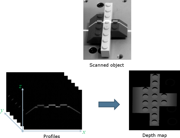
레이저 선 추출(LLE) 알고리즘은 카메라 센서에 의해 캡쳐된 물체의 일련의 프로파일로부터 깊이 맵을 생성하는 데 필요합니다.
LLE 알고리즘의 목적은 사용자 정의 관심 영역 (ROI) 내에서 센서 프레임의 모든 열에서 수직 프로파일을 따라 라인 위치를 측정하는 것입니다.
객체 위치의 모든 단계에서 감지는 프레임의 각 열을 개별적으로 분석하고 그레이 값으로 저장된 출력 위치 행을 생성합니다.
아래 그림은 깊이 맵 생성을 보여줍니다.
The class ELaserLineExtractor provides the laser line extraction functionality in Open eVision.
Uses the method ELaserLineExtractor.AnalysisMode to select one of the following algorithms to extract the laser line (see below for more details):
| □ | 최대 감지는 최대 강도의 픽셀 위치를 반환합니다. 가장 빠른 방법이지만 서브 픽셀 정밀도는 지원하지 않습니다. |
| □ | 피크 검출 방식은 국소 최대값을 검출합니다. 여러 개의 최대값이 검출되면 가장 놓은 강도를 가진 값이 반환됩니다. 위치는 서브 픽셀 정밀도로 반환됩니다. |
| □ | 중심선 알고리즘은 레이저 선이 여러 픽셀에 걸쳐 있을 때 적합합니다. 위치는 서브 픽셀 정밀도로 반환됩니다. |
낮은 강도의 픽셀을 제외하도록 임계값을 설정할 수도 있습니다.
레이저 선 추출 알고리즘에 의해 반환된 선 위치는 관심 영역 하단과 관련이 있습니다. 그래서 깊이 맵의 값은 0(ROI의 아래쪽)에서 ROI 높이까지의 범위에 있습니다.

레이저 라인 추출 메서드
최대 감지
최대 감지 알고리즘은 ROI 열의 모든 픽셀을 분석하여 최대 강도를 갖는 픽셀을 결정합니다. 아래 그림은 주어진 ROI 열의 레이저 선 위치를 보여줍니다.
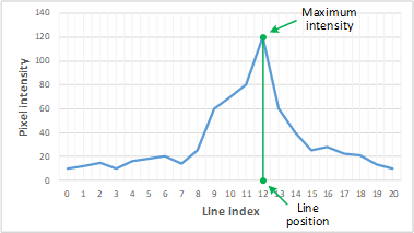
ROI 프로파일의 최대 감지
또한 처리 체인에 포함시키는 것이 좋습니다:
| □ | 이미지의 고주파 변동을 줄이기 위한 저역 통과 필터. |
| □ | 센서에서 배경 잡음을 제거하기 위한 임계 값. |
피크 감지
피크 감지 알고리즘은 1차 미분 함수의 이산적 단순화에 의존합니다.

f'(x)는 를 따라 주어진 의 기울기를 출력합니다.f(x)x
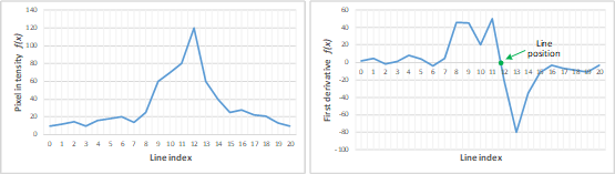
f(x) 및 플f'(x)롯
우리는 f’(x)가 두 포인트 양식 라인 방정식을 기반으로 신호를 변경하는 위치를 감지하여 라인 위치를 계산합니다.

여기서 (x1, y1)와 (x2, y2)는 x2≠ x1가 있는 행의 두 점이므로 y = 0에 대해 다음 방정식을 얻습니다:

중력의 중심
중력의 중심(CoG) 메서드는 이미지 객체의 질량 중심을 계산하는 알고리즘을 사용합니다. 또한 ‘평면체의 중심’이라고 알려진 중력의 중심(CoG)은 다음 방정식에 의해 구할 수 있습니다:


여기서  및
및  는 CoG의 좌표이고 a는 x 및 y 축의 픽셀 강도입니다.
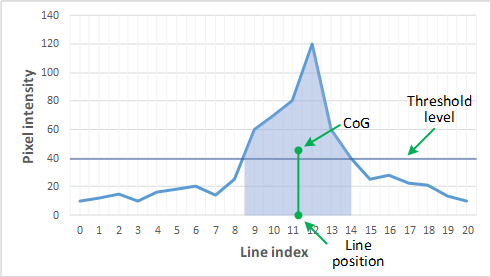
ROI 프로파일에서 중력의 중심
저역 통과 선형 필터
선택적으로 이미지의 노이즈 및 고주파를 줄이기 위해 선 추출 앞에 로우 패스 선형 필터를 적용할 수 있습니다.
저역 통과 필터는 1 x 3 슬라이딩 윈도우에 컨볼루션 연산자를 적용합니다. 컨볼루션 커널 (A, B, C)의 세 요소는 구성 가능하며 양의 정수를 허용합니다. 아래 그림은 주어진 ROI 내에서 컨볼루션 커널 요소의 위치를 보여줍니다.

ELaserLineExtractor::SetEnableSmoothing(true/false) 메서드로 레이저 선 추출 방법에 대해 저역 통과 필터를 활성화할 수 있습니다. Parameters A, B and C are set with ELaserLineExtractor::SetSmoothingParameters(A, B, C).
Depth map Z resolution
| ● | As explained above, the laser line extraction computes the sub-pixel position of the laser line profile for each column of the region of interest. |
| □ | This position is encoded in a 16-bit depth map (EDepthMap16). |
| □ | The resolution controls the way the sub-pixel positions are converted to 16-bit fixed point values (that is how many bits are allocated to represent the fractional part of the sub-pixel position). |
| □ | On a EDepthMap16, use the method EDepthMap16.ZResolution to retrieve the resolution. It is a floating-point value used to convert the integer pixel value to a real depth value. |
| ● | By default, ELaserLineExtractor computes the best resolution depending on the height of the region of interest. The following table lists typical resolution values depending on the height of the processed frame or region of interest. |
|
Frame or ROI height |
Bits used for the fractional part |
Z resolution |
|---|---|---|
|
100 |
8 |
1/256 = 0.00390625 |
|
200 |
8 |
1/256 = 0.00390625 |
|
400 |
7 |
1/128 = 0.0078125 |
|
800 |
6 |
1/64 = 0.015625 |
|
2500 |
4 |
1/16 = 0.0625 |
| ● | Use the optional parameter zResolution of the constructor ELaserLineExtractor.ElaserLineExtractor to fix the Z resolution. |
| □ | If you do not set the parameter zResolution, an algorithm computes the optimal value. Use ElaserLineExtractor.DepthMap to query the returned depth map and get the effective resolution. |
| ● | If you are using the hardware laser line extraction with the Coaxlink Quad 3D-LLE, the fixed point format is set by the configuration: 8_8 or 11_5 for 8- or 5-bit fractional part. |
| 2 | See documentation.euresys.com/Products/COAXLINK/COAXLINK/en-us/Content/03_Interfaces/functional-guide/lle/LLE_Processing_Core_Characteristics.htm |