
测量PCB的翘曲
名为3DPCBWarpage的C++样本程序,提供此应用实例:
| □ | 此源码位于Sample Programs\MsVc samples\3DPCBWarpage。 |
| □ | 实例图像位于Sample Images\Easy3D\PCB Warpage。 |
注意: 您需要Easy3D和EasyGauge许可,才能运行此应用程序。
显示此3D PCB翘曲应用实例输出
注意: 本文档未描述校准步骤。 我们假设已完成校准,且使用的公制单位为毫米。
本应用程序演示了如何测量PCB翘曲。
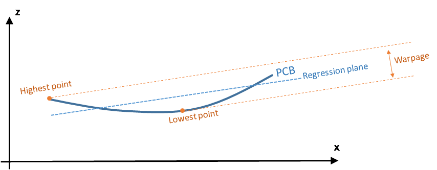
在此应用中,我们将翘曲定义为当PCB回归平面为水平方向时最高和最低表面点之差。 换句话说,我们通过PCB点拟合一个平面,并取此回归平面上方最高点与下方最低点之间的垂直距离。
主要步骤如下:
| 1. | 利用一个典型PCB平面的首次测定,来制作初始ZMap。 |
| 2. | 通过以下方式过滤数据: |
| □ | 移除其邻近显示出较大高度偏差的点。 |
| □ | 对其余点应用平滑过滤器。 |
为了生成最终的ZMap,此应用程序将通过余下/过滤数据拟合一个回归平面。
| 3. | 在ZMap上,通过检测PCB的角进行对齐(可选)。 |
| 4. | 从而生成应用程序用来计算PCB翘曲的最终ZMap。 |
对于PCB边缘(可选)对齐,应确保生成的ZMap始终保持不变,并与测量期间PCB方向无关。
而且,在最终的ZMap中,水平线应与PCB回归平面平行。 这对定义明确的翘曲值是必要的。
| 5. | 使用校准模型(此代码中的model_)和深度图(dm_),此应用程序会生成一个点云(pc_)。 |
或者,您直接从文件加载点云。
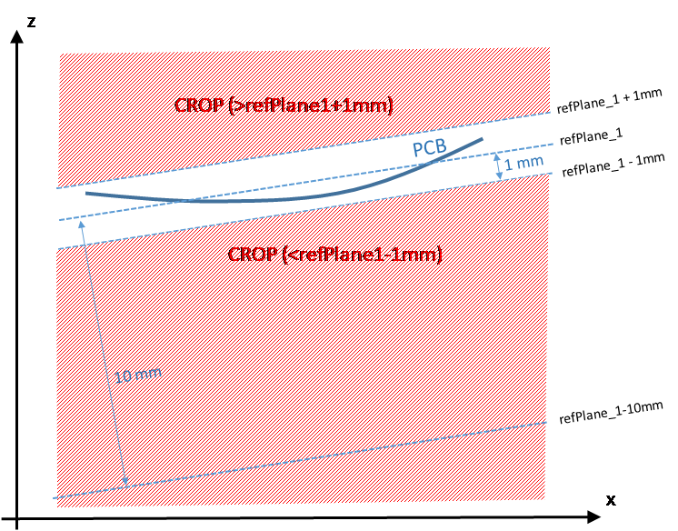
| 6. | 在这个点云中,应用程序通过使用E3DPlaneFinder类型的平面查找器对象,搜索最大平面来定位PCB平面。 由于我们要处理弯曲的PCB,因此平面查找器对象使用了较大的公差(+/-1毫米)。 |
此步骤将生成名为refPlane_1的参考平面,类型为E3DPlane。
| 7. | 此应用程序会裁剪距离参考平面远于1毫米的数据点。 |
| 8. | 它使用refPlane_1生成首个ZMap(称作zmapBeforeAlignment)。 实际上,用于生成ZMap的参考平面比refPlane_1低10 mm,因此ZMap的所有像素值均为正值。 如下图所示。 |
以下显示了生成ZMapzmapBeforeAlignment的代码。
// Apply calibration to the depth map, a metric 3D point cloud is generated
E3DDepthMapToPointCloudConverter converter;
converter.SetCalibrationModel(model_);
converter.Convert(dm_, pc_);
// Search for the PCB plane
float maximumDistanceToPlane = 1.0f; // 1.0 mm
E3DPlaneFinder finder(maximumDistanceToPlane); // tolerance for plane search = 1.0 mm
E3DPlane refPlane_1 = finder.Find(pc_); // finds the largest plane in the point cloud
// Crop any point distant from PCB plane
E3DPlaneCropper cropperPCB(refPlane_1); // 'refPlane_1' = ref. plane for the cropper
E3DPointCloud pcPlaneOnly; // only keep points close to the ref. plane
cropperPCB.Crop(pc_, pcPlaneOnly, EPlaneCropperType_KeepClose, maximumDistanceToPlane);
// ZMap projection of PCB plane, using reference plane and fixed resolution
float zMapPixelSize = 0.050f; // ZMap horizontal resolution: 1 pixel = 50µm = 0.050 mm
float zMapVerticalResolution = 0.001f; // ZMap vertical resol.: 1 gray value = 1µm (= 0.001 mm)
float zMapOffset = 10.0f; // 10 mm
E3DZMapGenerator zmapGenerator;
EZMap16 zmapBeforeAlignment;
zmapGenerator.SetScale(zMapPixelSize); // horizontal resolution = 50µm/pixel
zmapGenerator.SetZScale(zMapVerticalResolution); // vertical resolution = 1 µm/GV
zmapGenerator.SetReferencePlane(refPlane_1 - zMapOffset); // 10mm below refPlane_1
zmapGenerator.SetOrientationVectorMode(EZMapOrientationVectorMode_XAxis);
zmapGenerator.SetExtension(1.f); // add a 1mm 3D extension, create a border around the ZMap
zmapGenerator.Convert(pcPlaneOnly, zmapBeforeAlignment);
int zmapWidth = zmapBeforeAlignment.GetWidth();
int zmapHeight = zmapBeforeAlignment.GetHeight();
下图显示了每像素分辨率为16位的首个ZMap。
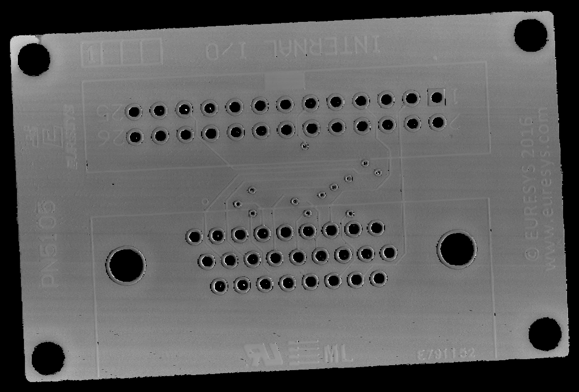
ZMap zmapBeforeAlignement
在该图中:
| □ | 背景像素的值为“0”(黑色)。 该值保留为“未定义像素”(未检测到)。 具有不同于零值的像素是“有效像素”。 |
| □ | 对于一个灰度值,水平分辨率设置为50μm/像素,垂直分辨率设置为1μm。 |
由于ZMap的参考平面位于PCB下方10 mm处,图像中的平均灰度值为10000(10000灰度值= 10000μm)。
| □ | 没有指定该ZMap的大小;它会根据边界框的大小自动计算出来,并增大1mm,以便PCB周围有黑色边框。 这个增大由ZMap生成器的SetExtension方法指定。 PCB周围的黑色边框有助于检测边缘。 |
在计算ZMap上的翘曲时,此应用程序应忽略以下点:
| □ | 背景上的孤立噪音点。 |
| □ | 孔内或垫上的噪音点。 |
此应用程序会删除这些点,并在余下的点上执行低通过滤器,只检测蠕动/全局PCB变形。 这个过滤分两步完成。
过滤器 1:删除异常值
| 1. | 过滤器RemoveNoise定义了在ZMap每个像素上移动的内核窗口。 |
| 2. | 对于ZMap图像的每个像素,内核窗口以该像素为中心,以过滤条件决定中心像素是保留还是移除。 |
这里使用的过滤条件是 E3DNoiseRemovalMethod_AbsoluteDifferenceFromMean;它将中心像素的值与内核窗口中所有有效像素的平均值进行比较。
如下图所示。
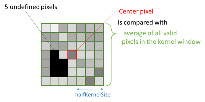
此应用程序评估保留或移除中心像素的条件,如下所示:
| □ | 如果窗口的定义像素少于25%(请参阅代码中的ratioValidPixelsFilter),或者如果中心像素先前未定义,则此中心像素标记为未定义。 |
| □ | 此应用程序计算有关内核窗口中所有有效点的中心点的高度偏差,如果得到的高度偏差超过30μm(请参阅代码中的thresholdFilter),则此应用程序会移除内核窗口中心像素(事实上,会把它替换为0,即未定义的像素)。 |
过滤器 2:应用平均过滤器
| 1. | 第二步,此应用程序应用平均滤波器(低通)以消除随机噪声。 |
| 2. | 过滤器ComputeAverageMap也定义了在每个像素上移动的内核窗口。 |
| 3. | 如果窗口内有足够的有效像素(在此情况下至少为25%),并且中心像素有效,则此中心像素会被内核窗口内所有像素的平均值所取代。 |
筛选代码
过滤ZMap数据的代码为:
// Process the ZMap to remove noise and small scale structures
// Filters parameters
int halfKernelSizeFilter = 25; // kernel size = 2 x halfKernelSizeFilter + 1 pixel = 51
float thresholdFilter = 0.030f; // threshold = maximum deviation from mean
float ratioValidPixelsFilter = 0.25f; // requires at least 25% of valid points in the kernel
// Apply noise removal filter
EZMap16 zmapBeforeAlignmentFilter1; // output of the filter
zmapBeforeAlignmentFilter1.SetSize(zmapBeforeAlignment);
Easy3D::RemoveNoise(zmapBeforeAlignment, zmapBeforeAlignmentFilter1,
E3DNoiseRemovalMethod_AbsoluteDifferenceFromMean,
halfKernelSizeFilter, thresholdFilter, ratioValidPixelsFilter, false);
// Apply low-pass filter
EZMap16 zmapBeforeAlignmentFilter2; // output of the second filter
zmapBeforeAlignmentFilter2.SetSize(zmapBeforeAlignment);
Easy3D::ComputeAverageMap(zmapBeforeAlignmentFilter1, zmapBeforeAlignmentFilter2,
halfKernelSizeFilter, ratioValidPixelsFilter);
过滤的步骤如下所示:
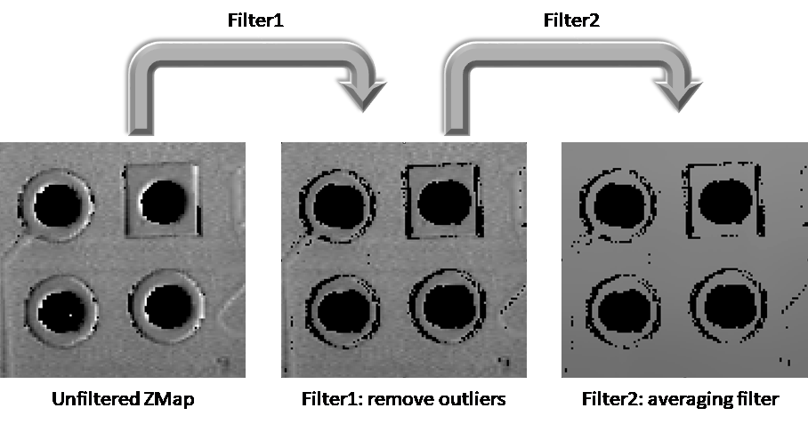
ZMap过滤的两个步骤
此可选步骤包括找到PCB的方向(检测矩形)。
我们可以跳过这一步来计算翘曲,但边缘对齐会使得不同ZMaps之间的对比更加容易。
如需生成与PCB边缘对齐的ZMap:
| 1. | 此应用程序将ZMap转换为8位图像。 须使用2D工具集Open eVision。 |
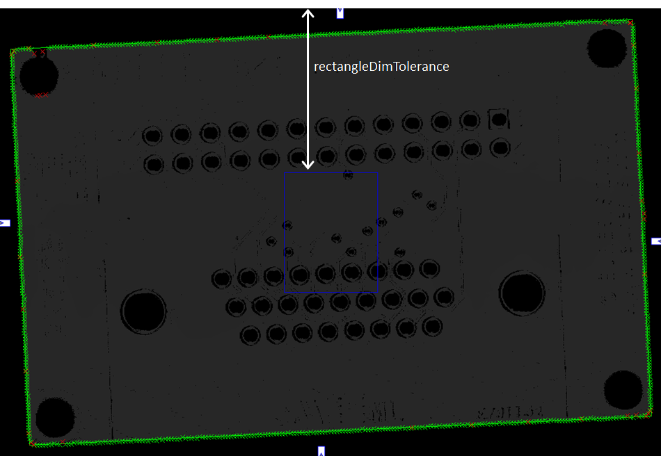
| 2. | 使用EasyGauge,通过拟合ZMap图像上的矩形,来检测PCB的边缘。 |
此应用程序使用未定义(0)和有效(非零)像素之间的转换,来检测矩形边缘的位置。
ZMap图像上的矩形量器的使用如下所示:
对应的代码为:
// From the ZMap create an 8-bit image for alignment
EImageBW8 imageBeforeAlignment8(zmapWidth, zmapHeight);
// conversion 16-bits to 8-bits
EasyImage::Convert(&zmapBeforeAlignmentFilter2.AsEImage(), &imageBeforeAlignment8);
// Search for the PCB "rectangle" in 8-bits image
float rectangleDimTolerance = 500.f; // 500 pixels tolerance on the rectangle's dimension
ERectangleGauge ERectangleGauge1;
ERectangle measuredRectangle;
ERectangleGauge1.SetTolerance(rectangleDimTolerance);
ERectangleGauge1.SetSize((float)(zmapWidth), (float)(zmapHeight));
ERectangleGauge1.SetThreshold(20);
ERectangleGauge1.SetCenterXY((float)(zmapWidth / 2.0), (float)(zmapHeight / 2.0));
ERectangleGauge1.SetTransitionChoice(ETransitionChoice_NthFromBegin);
ERectangleGauge1.SetTransitionIndex(0); // take the first transition ...
ERectangleGauge1.SetTransitionType(ETransitionType_Bw); // ... from black to white
ERectangleGauge1.SetNumFilteringPasses(10);
ERectangleGauge1.SetFilteringThreshold(5.0f); // threshold = 5 x the mean deviation
ERectangleGauge1.Measure(&imageBeforeAlignment8);
measuredRectangle = ERectangleGauge1.GetMeasuredRectangle();
float rectangleSizeX = ceil(measuredRectangle.GetSizeX()); // will be the width of the final ZMap
float rectangleSizeY = ceil(measuredRectangle.GetSizeY()); // will be the height of the final ZMap
// Store the 3D coordinates of the aligned rectangle corners
EPoint corner_2D[4];
E3DPoint corner_3D[4];
measuredRectangle.GetCorners(corner_2D[0], corner_2D[1], corner_2D[2], corner_2D[3]);
for (int i = 0; i<4; i++)
{
E3DPoint cornerPtZMap;
cornerPtZMap = E3DPoint(corner_2D[i].GetX(), // X pixel position
corner_2D[i].GetY(), // Y pixel position
zMapOffset / zMapVerticalResolution); // = 10000 (height of the ZMap reference plane)
zmapBeforeAlignmentFilter2.PixelToWorld(cornerPtZMap, corner_3D[i]);
}
| 1. | 为了创建一个新的具有明确定义的参考平面ZMap(与通过滤波点的回归平面平行),此应用程序从平滑的ZMap生成一个点云。 |
在以下代码中,被过滤的点云被命名为filteredPc:
// From the filtered ZMap, generate a new 3D point cloud
// Use that point cloud to estimate a better reference plane
E3DPointCloud filteredPc;
zmapBeforeAlignmentFilter2.ToPointCloud(filteredPc);
E3DPlaneFitter planeFitter;
E3DPlane refPlane_2 = planeFitter.Fit(filteredPc); // find the best fit plane
| 2. | 此应用程序通过筛选的数据点拟合一个平面(最终回归平面称为refPlane_2)。 |
| 3. | 这个与refPlane_1非常接近的新参考平面,是用于生成最终的ZMap(用于计算翘曲)的新“水平”参考平面。 |
这个平面对原始数据中发现的噪音和异常值要敏感得多。
| 1. | 此应用程序使用过滤点云来创建最终的ZMap。 |
该新ZMap的位置基于:
| □ | 平面Ref_plane2减去10mm作为参考平面。 |
| □ | 角的3D位置决定了参考角(左下)和新的水平方向(X轴)。 使用角位置,我们指定产生新ZMap的原点和方向矢量,假定两个平面彼此非常接近。 |
生成该对齐ZMap的代码如下:
// Generate the new ZMap with the filtered data
EZMap16 zmap_;
zmapGenerator.SetOrigin(corner_3D[2]);
zmapGenerator.SetReferencePlane(refPlane_2 - zMapOffset); // refPlane_2 – 10mm
E3DPoint horizDirection(corner_3D[1].X - corner_3D[0].X,
corner_3D[1].Y - corner_3D[0].Y,
corner_3D[1].Z - corner_3D[0].Z);
zmapGenerator.SetOrientationVector(horizDirection);
zmapGenerator.SetResolution((int)rectangleSizeX, (int)rectangleSizeY);
zmapGenerator.SetExtension(0.f); // no border
zmapGenerator.Convert(filteredPc, zmap_);
| 2. | 如需计算PCB的翘曲,此应用程序只需从对齐的ZMap中获取最大和最小高度。 |
它采用Easy3D类中的静态方法 ComputeStatistics,来检索这些值。
对应的代码为:
// Calculate warpage in metric unit
UINT32 validCount;
float minValue, maxValue, averageValue;
Easy3D::ComputeStatistics(zmap_, validCount, minValue, maxValue, averageValue);
float warpage = maxValue - minValue;
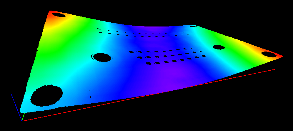
| ● | 此示例应用程序以3D形式显示PCB,并应用了颜色映射。 |
| ● | 此3D查看器在Z轴上应用比例因子10来强调翘曲。 |
所得深度图(显示翘曲)的三维效果图,及其相应的翘曲测量,示例如下所示:
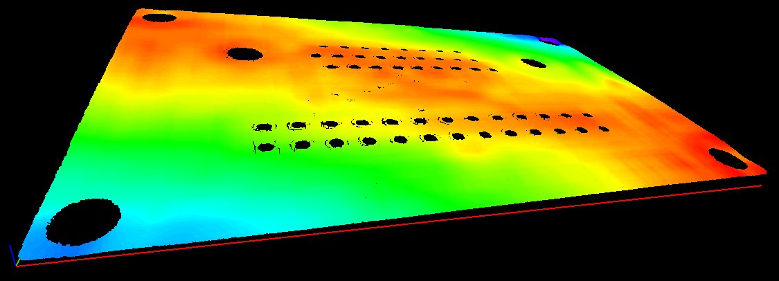
翘曲= 0.145毫米
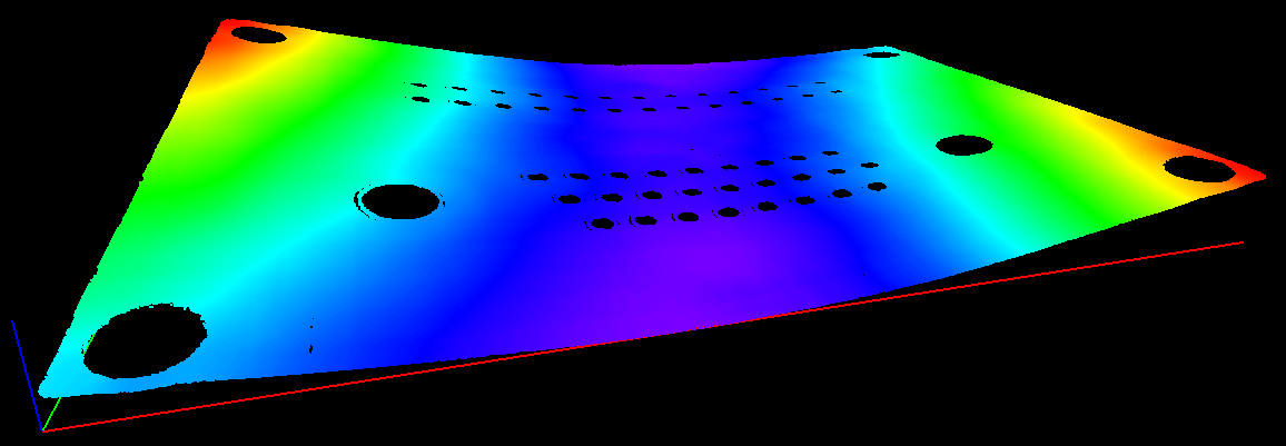
翘曲= 0.407毫米
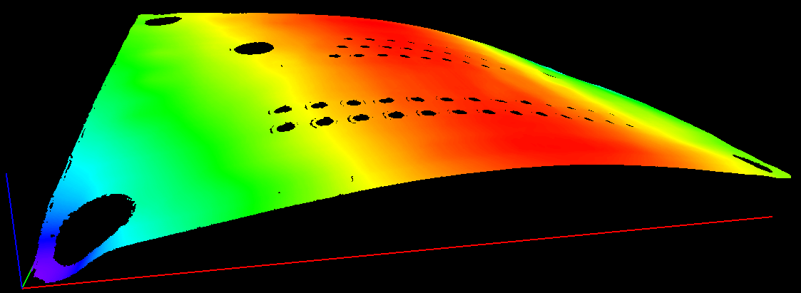
翘曲= 0.620毫米