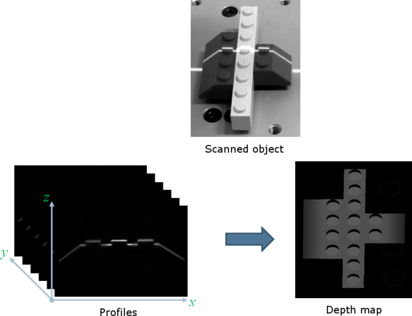
A Laser Line Extraction (LLE) algorithm is required to create a depth map from a sequence of profiles of the object captured by the camera sensor.
The objective of an LLE algorithm is to measure the line position along a vertical profile in every column of a sensor frame, within a user-defined region of interest (ROI).
For every step of the object position, the detection analyzes each column of a frame individually and produces a row of output positions, stored as gray values.
The figure below illustrates a depth map generation.
The class ELaserLineExtractor provides the laser line extraction functionality in Open eVision.
Uses the method ELaserLineExtractor.AnalysisMode to select one of the following algorithms to extract the laser line (see below for more details):
| □ | Maximum detection returns the position of the pixel of maximum intensity. It’s the fastest method but it doesn’t support sub-pixel precision. |
| □ | Peak detection approach detects local maxima. If several maxima are detected, the one with the highest intensity is returned. The position is returned with sub-pixel precision. |
| □ | Center of gravity algorithm is suitable when the laser line is spread over several pixels. The position is returned with sub-pixel precision. |
You can also set a threshold to exclude pixels with low intensity.
The line position returned by the laser line extraction algorithms is relative to the bottom of the region of interest. So, values in the depth map range from 0 (bottom of the ROI) to the height of the ROI.

Laser line extraction methods
Maximum detection
The maximum detection algorithm analyzes all the pixels in a ROI column to determine the one with the maximum intensity. The figure below shows the laser line position on a given ROI column.
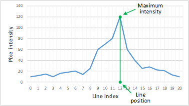
Maximum detection on a ROI profile
We also recommend to include in the processing chain:
| □ | A low-pass filter to reduce the high frequency variations in the image. |
| □ | A threshold to eliminate the background noise from the sensor. |
Peak detection
The peak detection algorithm relies on a discrete simplification of the first derivative function.

The f'(x) outputs the slope of a given f(x) along the x.
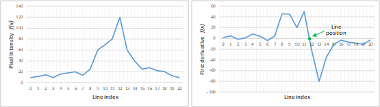
f(x) and f'(x) plots
We compute the line position by detecting where f’(x) changes its signal based on the two-point form line equation:

where (x1, y1) and (x2, y2) are two points on the line with x2≠ x1, we obtain the following equation for y = 0:

Center of gravity
The center of gravity (CoG) method uses an algorithm that calculates the center of mass of an image object. Also known as "centroid of plane figures", the CoG is obtained by the following equations:


where  and
and  are the coordinates of the CoG and a is the pixel intensity along the x and y axes.
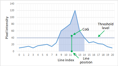
Center of gravity on a ROI profile
Low-pass linear filter
Optionally, you can apply a low-pass linear filter in front of the line extraction in order to reduce noise and high frequencies in the image.
The low-pass filter applies a convolution operator on a 1 x 3 sliding window. The 3 elements of the convolution kernel (A, B and C) are configurable, accepting any positive integer. The figure below illustrates the positioning of the convolution kernel elements within a given ROI.

You can activate the low-pass filter for any of the laser line extraction methods with the method ELaserLineExtractor.EnableSmoothing(true/false). Parameters A, B and C are set with ELaserLineExtractor.SetSmoothingParameters(A, B, C).
Depth map Z resolution
| ● | As explained above, the laser line extraction computes the sub-pixel position of the laser line profile for each column of the region of interest. |
| □ | This position is encoded in a 16-bit depth map (EDepthMap16). |
| □ | The resolution controls the way the sub-pixel positions are converted to 16-bit fixed point values (that is how many bits are allocated to represent the fractional part of the sub-pixel position). |
| □ | On a EDepthMap16, use the method EDepthMap16.ZResolution to retrieve the resolution. It is a floating-point value used to convert the integer pixel value to a real depth value. |
| ● | By default, ELaserLineExtractor computes the best resolution depending on the height of the region of interest. The following table lists typical resolution values depending on the height of the processed frame or region of interest. |
|
Frame or ROI height |
Bits used for the fractional part |
Z resolution |
|---|---|---|
|
100 |
8 |
1/256 = 0.00390625 |
|
200 |
8 |
1/256 = 0.00390625 |
|
400 |
7 |
1/128 = 0.0078125 |
|
800 |
6 |
1/64 = 0.015625 |
|
2500 |
4 |
1/16 = 0.0625 |
| ● | Use the optional parameter zResolution of the constructor ELaserLineExtractor.ElaserLineExtractor to fix the Z resolution. |
| □ | If you do not set the parameter zResolution, an algorithm computes the optimal value. Use ElaserLineExtractor.DepthMap to query the returned depth map and get the effective resolution. |
| ● | If you are using the hardware laser line extraction with the Coaxlink Quad 3D-LLE, the fixed point format is set by the configuration: 8_8 or 11_5 for 8- or 5-bit fractional part. |
| 2 | See documentation.euresys.com/Products/COAXLINK/COAXLINK/en-us/Content/03_Interfaces/functional-guide/lle/LLE_Processing_Core_Characteristics.htm |