
Measuring the Warpage of a PCB
This application example is provided as a C++ sample program, named 3DPCBWarpage:
| □ | The source code is located in Sample Programs\MsVc samples\3DPCBWarpage. |
| □ | The sample images are located in Sample Images\Easy3D\PCB Warpage. |
Note: To run this program, you need the Easy3D and EasyGauge licenses.
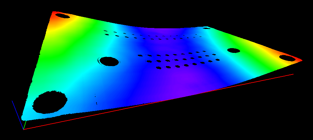
Display output of the 3D PCB Warpage application example
Note: The calibration process is not described in this document. We assume that a calibration has been done and that the metric unit used is the mm.
This application demonstrates how to measure the warpage of a PCB.
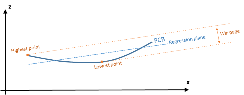
In this application, we define the warpage as the difference between the highest and the lowest surface points when the PCB regression plane is oriented horizontally. In other words, we fit a plane through the PCB points and take the perpendicular distance between the highest point above and the lowest point below this regression plane.
The main steps of the process are:
| 1. | Making an initial ZMap using a first estimation of an average PCB plane. |
| 2. | Filtering the data by: |
| □ | Removing the points that show a large height deviation with respect to their neighbors. |
| □ | Applying a smooth filter on the remaining points. |
For the generation of the final ZMap, the application will fit a regression plane through the remaining / filtered data.
| 3. | On the ZMap, detecting the corners of the PCB for the alignment (optional). |
| 4. | Producing the final ZMap that the application will use to compute the warpage of the PCB. |
The (optional) alignment on the PCB edges ensures that the resulting ZMap is always the same, independently of the orientation of the PCB during the measurement.
Moreover, on the final ZMap, the horizon is parallel with the PCB regression plane. This is necessary to have a well-defined warpage value.
| 5. | Using a calibration model (model_ in the code) and a depth map (« dm_ »), the application produces a point cloud (« pc_ »). |
Alternatively, you can load directly a point cloud from a file.
| 6. | In this point cloud, the application localizes the PCB plane by searching for the largest plane, using a plane finder object of the type E3DPlaneFinder. As we want to handle a curved PCB, a large tolerance (+/- 1mm) is used by the plane finder object. |
This step produces a reference plane called refPlane_1 of the type E3DPlane.
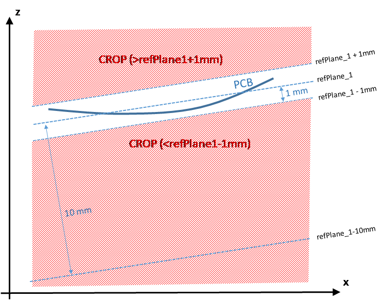
| 7. | The application crops any data point that is farther from the reference plane than 1 mm. |
| 8. | It uses refPlane_1 » to generate the first ZMap (called zmapBeforeAlignment). Actually, the reference plane used for the ZMap generation is 10 mm below refPlane_1 so that all pixel values of the ZMap are positive. This is illustrated on the figure below. |
The code to produce the ZMap zmapBeforeAlignment is shown below.
// Apply calibration to the depth map, a metric 3D point cloud is generated
E3DDepthMapToPointCloudConverter converter;
converter.SetCalibrationModel(model_);
converter.Convert(dm_, pc_);
// Search for the PCB plane
float maximumDistanceToPlane = 1.0f; // 1.0 mm
E3DPlaneFinder finder(maximumDistanceToPlane); // tolerance for plane search = 1.0 mm
E3DPlane refPlane_1 = finder.Find(pc_); // finds the largest plane in the point cloud
// Crop any point distant from PCB plane
E3DPlaneCropper cropperPCB(refPlane_1); // 'refPlane_1' = ref. plane for the cropper
E3DPointCloud pcPlaneOnly; // only keep points close to the ref. plane
cropperPCB.Crop(pc_, pcPlaneOnly, EPlaneCropperType_KeepClose, maximumDistanceToPlane);
// ZMap projection of PCB plane, using reference plane and fixed resolution
float zMapPixelSize = 0.050f; // ZMap horizontal resolution: 1 pixel = 50µm = 0.050 mm
float zMapVerticalResolution = 0.001f; // ZMap vertical resol.: 1 gray value = 1µm (= 0.001 mm)
float zMapOffset = 10.0f; // 10 mm
E3DZMapGenerator zmapGenerator;
EZMap16 zmapBeforeAlignment;
zmapGenerator.SetScale(zMapPixelSize); // horizontal resolution = 50µm/pixel
zmapGenerator.SetZScale(zMapVerticalResolution); // vertical resolution = 1 µm/GV
zmapGenerator.SetReferencePlane(refPlane_1 - zMapOffset); // 10mm below refPlane_1
zmapGenerator.SetOrientationVectorMode(EZMapOrientationVectorMode_XAxis);
zmapGenerator.SetExtension(1.f); // add a 1mm 3D extension, create a border around the ZMap
zmapGenerator.Convert(pcPlaneOnly, zmapBeforeAlignment);
int zmapWidth = zmapBeforeAlignment.GetWidth();
int zmapHeight = zmapBeforeAlignment.GetHeight();
The following image shows this first ZMap with a 16-bit per pixel resolution.
ZMap zmapBeforeAlignement
In this image:
| □ | Background pixels have the value "0" (black). This value is reserved for “undefined pixels” (nothing detected). Pixels having a value different from zero are “valid pixels”. |
| □ | The horizontal resolution is set to 50 µm/pixel and the vertical resolution is set to 1 µm for one gray value. |
Because the reference plane of the ZMap is 10 mm below the PCB, the average gray value in the image is 10000 (10000 gray values = 10000 µm).
| □ | The size of this ZMap is not specified; it is automatically computed from the size of the bounding box, enlarged by 1 mm so that there is a black border around the PCB. This enlargement is specified by the method SetExtension of the ZMap generator. The black border around the PCB helps for the detection of the edges. |
On the ZMap, the application should ignore the following points during the computation of the warpage:
| □ | Isolated noisy points on the background. |
| □ | Noisy points inside the holes or on the pads. |
The application removes points and applies a low-pass filter on the remaining points to detect only the slow / global PCB deformations. This filtering is done in 2 steps.
Filter 1: removing the outliers
| 1. | The filter RemoveNoise defines a kernel window that is moved over every pixel of the ZMap. |
| 2. | For each pixel of the ZMap image, the kernel window is centered on this pixel and the filter condition determines if the center pixel is either kept or removed. |
The filter condition used here is E3DNoiseRemovalMethod_AbsoluteDifferenceFromMean; it compares the value of the pixel in the center with the average of all valid pixels in the kernel window.
This is illustrated on the figure below.
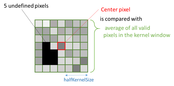
The application evaluates the condition to keep or remove the center pixel as follow :
| □ | If a window has less than 25% of defined pixels (see ratioValidPixelsFilter in the code) or if the center pixel is already undefined, this center pixel is marked as undefined. |
| □ | The application computes the height deviation of the center point with respect to all the valid points in the kernel window and, if the resulting height deviation exceeds 30 µm (see thresholdFilter in the code), the application removes the pixel in the center of the kernel window (it actually replaces it by 0, meaning « undefined pixel »). |
Filter 2: applying an averaging filter
| 1. | In a second step, the application applies an averaging filter (low-pass) in order to remove the random noise. |
| 2. | The filter ComputeAverageMap also defines a kernel window that is moved over every pixel. |
| 3. | If there are enough valid pixels within the window (at least 25% in this case) and if the center pixel is valid, this center pixel is replaced by the average of all pixels within the kernel window. |
Filtering code
The code used for the filtering of the ZMap data is:
// Process the ZMap to remove noise and small scale structures
// Filters parameters
int halfKernelSizeFilter = 25; // kernel size = 2 x halfKernelSizeFilter + 1 pixel = 51
float thresholdFilter = 0.030f; // threshold = maximum deviation from mean
float ratioValidPixelsFilter = 0.25f; // requires at least 25% of valid points in the kernel
// Apply noise removal filter
EZMap16 zmapBeforeAlignmentFilter1; // output of the filter
zmapBeforeAlignmentFilter1.SetSize(zmapBeforeAlignment);
Easy3D::RemoveNoise(zmapBeforeAlignment, zmapBeforeAlignmentFilter1,
E3DNoiseRemovalMethod_AbsoluteDifferenceFromMean,
halfKernelSizeFilter, thresholdFilter, ratioValidPixelsFilter, false);
// Apply low-pass filter
EZMap16 zmapBeforeAlignmentFilter2; // output of the second filter
zmapBeforeAlignmentFilter2.SetSize(zmapBeforeAlignment);
Easy3D::ComputeAverageMap(zmapBeforeAlignmentFilter1, zmapBeforeAlignmentFilter2,
halfKernelSizeFilter, ratioValidPixelsFilter);
The different steps of the filtering are illustrated below:
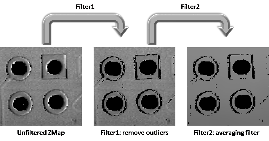
The 2 steps of the ZMap filtering
This optional step consists in finding the orientation of the PCB (detection of a rectangle).
We could skip this step for the computation of the warpage but aligning on the edges makes the comparison of different ZMaps with each other easier.
To generate a ZMap aligned on the PCB edges:
| 1. | The application converts the ZMap to an 8-bit image. This is necessary to use the 2D tool set of Open eVision. |
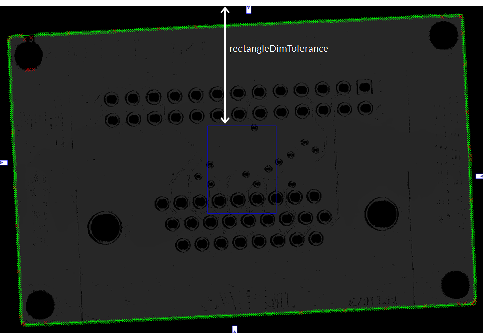
| 2. | Using EasyGauge, it detects the edges of the PCB by fitting a rectangle on the ZMap image. |
The application uses the transitions between the undefined (0) and the valid (non-zero) pixels to detect the position of the edges of the rectangle.
The use of a rectangular gauge on the ZMap image is illustrated below:
The corresponding code is:
// From the ZMap create an 8-bit image for alignment
EImageBW8 imageBeforeAlignment8(zmapWidth, zmapHeight);
// conversion 16-bits to 8-bits
EasyImage::Convert(&zmapBeforeAlignmentFilter2.AsEImage(), &imageBeforeAlignment8);
// Search for the PCB "rectangle" in 8-bits image
float rectangleDimTolerance = 500.f; // 500 pixels tolerance on the rectangle's dimension
ERectangleGauge ERectangleGauge1;
ERectangle measuredRectangle;
ERectangleGauge1.SetTolerance(rectangleDimTolerance);
ERectangleGauge1.SetSize((float)(zmapWidth), (float)(zmapHeight));
ERectangleGauge1.SetThreshold(20);
ERectangleGauge1.SetCenterXY((float)(zmapWidth / 2.0), (float)(zmapHeight / 2.0));
ERectangleGauge1.SetTransitionChoice(ETransitionChoice_NthFromBegin);
ERectangleGauge1.SetTransitionIndex(0); // take the first transition ...
ERectangleGauge1.SetTransitionType(ETransitionType_Bw); // ... from black to white
ERectangleGauge1.SetNumFilteringPasses(10);
ERectangleGauge1.SetFilteringThreshold(5.0f); // threshold = 5 x the mean deviation
ERectangleGauge1.Measure(&imageBeforeAlignment8);
measuredRectangle = ERectangleGauge1.GetMeasuredRectangle();
float rectangleSizeX = ceil(measuredRectangle.GetSizeX()); // will be the width of the final ZMap
float rectangleSizeY = ceil(measuredRectangle.GetSizeY()); // will be the height of the final ZMap
// Store the 3D coordinates of the aligned rectangle corners
EPoint corner_2D[4];
E3DPoint corner_3D[4];
measuredRectangle.GetCorners(corner_2D[0], corner_2D[1], corner_2D[2], corner_2D[3]);
for (int i = 0; i<4; i++)
{
E3DPoint cornerPtZMap;
cornerPtZMap = E3DPoint(corner_2D[i].GetX(), // X pixel position
corner_2D[i].GetY(), // Y pixel position
zMapOffset / zMapVerticalResolution); // = 10000 (height of the ZMap reference plane)
zmapBeforeAlignmentFilter2.PixelToWorld(cornerPtZMap, corner_3D[i]);
}
| 1. | In order to create a new ZMap with a well-defined reference plane (parallel with the regression plane through the filtered points), the application generates a point cloud from the smoothed ZMap. |
In the code below, the filtered point cloud is named filteredPc:
// From the filtered ZMap, generate a new 3D point cloud
// Use that point cloud to estimate a better reference plane
E3DPointCloud filteredPc;
zmapBeforeAlignmentFilter2.ToPointCloud(filteredPc);
E3DPlaneFitter planeFitter;
E3DPlane refPlane_2 = planeFitter.Fit(filteredPc); // find the best fit plane
| 2. | The application fits a plane (the final regression plane called refPlane_2) through the filtered data points. |
| 3. | This new reference plane, that is very close to refPlane_1, is the new « horizontal » reference for the generation of the final ZMap on which the warpage is computed. |
This plane is much less sensitive to the noise and outliers found in the original data.
| 1. | The application creates the final ZMap using the filtered point cloud. |
The position of this new ZMap is based on:
| □ | The plane Ref_plane2 minus 10 mm as the reference plane. |
| □ | The 3D position of the corners to determine the reference (lower-left) corner and the new horizontal orientation (X axis). Using the corner positions, we specify the origin and the orientation vector for the generation of the new ZMap, assuming that the two planes are very close to each other. |
The code that generates this aligned ZMap is:
// Generate the new ZMap with the filtered data
EZMap16 zmap_;
zmapGenerator.SetOrigin(corner_3D[2]);
zmapGenerator.SetReferencePlane(refPlane_2 - zMapOffset); // refPlane_2 – 10mm
E3DPoint horizDirection(corner_3D[1].X - corner_3D[0].X,
corner_3D[1].Y - corner_3D[0].Y,
corner_3D[1].Z - corner_3D[0].Z);
zmapGenerator.SetOrientationVector(horizDirection);
zmapGenerator.SetResolution((int)rectangleSizeX, (int)rectangleSizeY);
zmapGenerator.SetExtension(0.f); // no border
zmapGenerator.Convert(filteredPc, zmap_);
| 2. | To compute the warpage of the PCB, the application only needs the maximum and the minimum height from the aligned ZMap. |
It retrieves these values with the static method ComputeStatistics in the class Easy3D.
The corresponding code is:
// Calculate warpage in metric unit
UINT32 validCount;
float minValue, maxValue, averageValue;
Easy3D::ComputeStatistics(zmap_, validCount, minValue, maxValue, averageValue);
float warpage = maxValue - minValue;
| ● | The sample application displays the PCB in 3D and applies a color map. |
| ● | The 3D viewer applies a scale factor of 10 on Z axis to emphasize the warpage. |
Sample 3D renderings of the resulting depth maps (showing the warpage) and their corresponding warpage measurement are illustrated below:
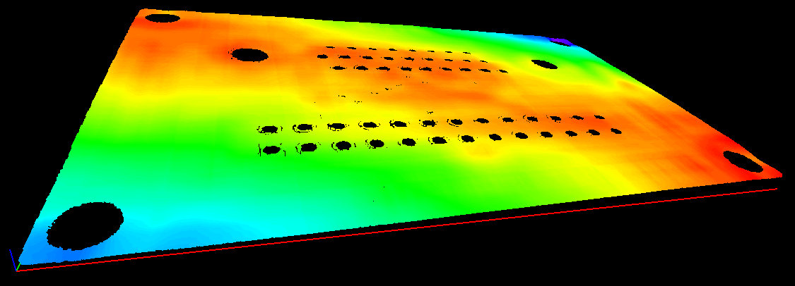
Warpage = 0.145 mm
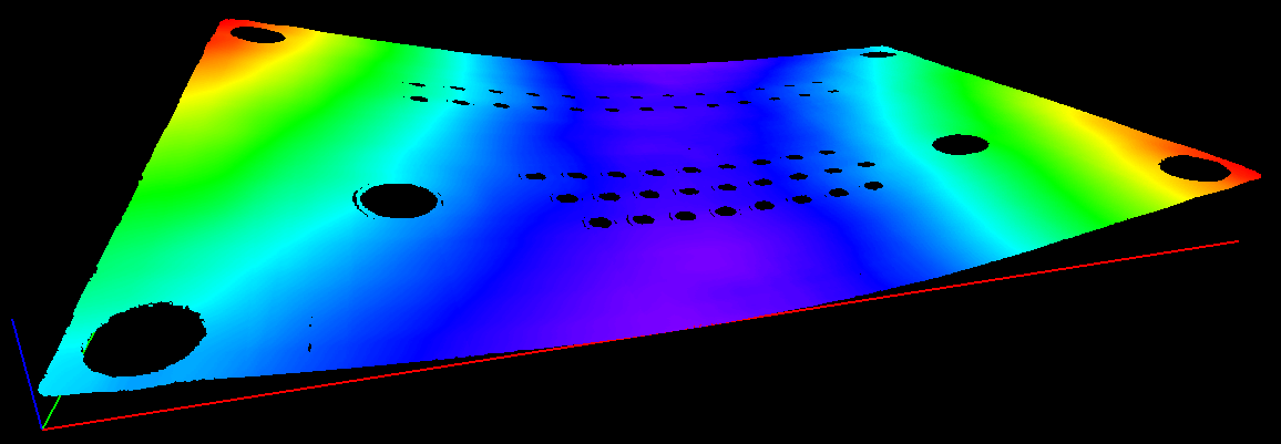
Warpage = 0.407 mm
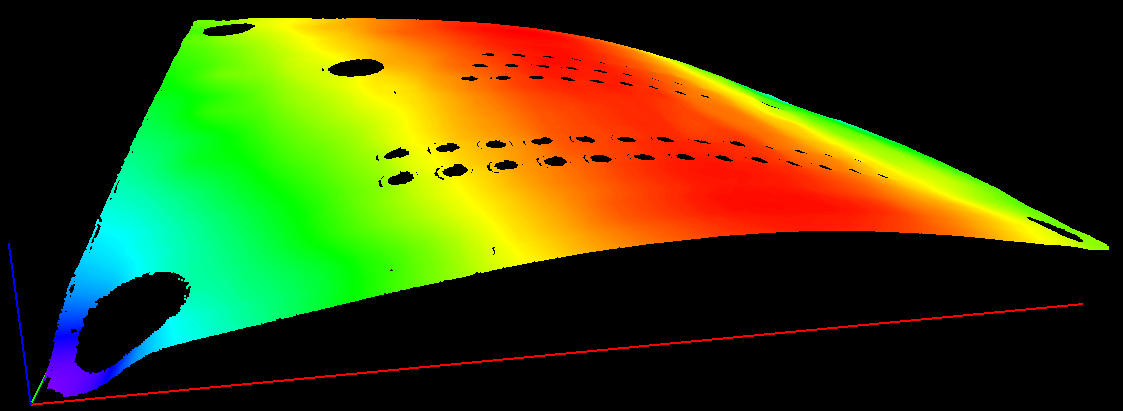
Warpage = 0.620 mm