
Measuring a Distorted Rectangle
Objective
Following this tutorial, you will learn how to use EasyGauge to perform measurements on a distorted rectangle component.
To obtain measurement results in physical units, we need to work in a calibrated field of view. You'll need first to load an image for calibration —a dot grid— (step 1), and calibrate the field of view (step 2). Then you'll load the distorted image (step 3), and attach a rectangle fitting gauge (step 4). The inspection is automatically performed (step 5). All measurement results are expressed in physical units.
Measuring a distorted rectangle
Step 1: Load the calibration image
| 1. | From the main menu, click EasyGauge, then New World Shape. |
| 2. | Keep the default variable name, and click OK. |
| 3. | In the Dot Grid Calibration tab, click the Open icon, and load the image file EasyGauge\Dot Grid 5.tif. This dot grid has been acquired in the same conditions and has the same distortion as the image we want to inspect. |
| 4. | Keep the default variable name for the new image object, and click OK. |
Step 2: Calibrate the field of view
| ● | Click Calibrate. From now on, the field of view is calibrated, and all results will be expressed in physical units. |
Step 3: Load the distorted image
| 1. | From the Gauges tab, click the Open icon, and load the image file EasyGauge\Distorted Component.tif. |
| 2. | Keep the default variable name, and click OK. |
Step 4: Attach a rectangle gauge to the image
| 1. | In the Gauges tab, right-click the world shape icon, and select New > Rectangle Gauge from the contextual menu. |
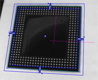
| 2. | Keep the default variable name, and click OK. The rectangle gauge dialog box is opened, and the rectangle gauge is drawn on the image. It consists of the following elements: |
| □ | A blue rectangular ring in which the rectangle is searched for. |
| □ | A blue nominal rectangle. |
| □ | Eleven white handles, allowing the user to move and extend the search area. |
| □ | Gray arrows, indicating in which direction segments are examined. |
| □ | Black and white rectangles, indicating which kind of transition are searched for. |
| □ | A green rectangle, indicating the rectangle found (if any). |
| 3. | Due to the perspective effect, the rectangle gauge doesn't look like a rectangle. Using the central handle, move the rectangle gauge in the image and observe the rectangle deformation. Due to the calibration, the rectangle gauge shape adapts to the field of view deformation. Extend the searching area, and adjust the nominal rectangle on the component edges. |
| 4. | In the Measurement tab of the rectangle gauge dialog box, select 'White To Black' from the Type dropdown list and 'From Begin' from the Choice dropdown list. |
Step 5: Perform the inspection
| 1. | The image is automatically inspected. However, clicking Process in the world shape dialog box will insert the corresponding code into the script window. |
| 2. | Click the Results tab to retrieve the measured X and Y sizes. All measurement results are expressed in physical units. |