Coaxial Cables: Attenuation vs. Frequency
Coaxial cables, or coax for short, were designed in the 19th century to eliminate signal interference between parallel cables. Modern coaxial cables are widely used to transmit and receive high-frequency electrical signals in a large spectrum of applications going from radio stations to high-speed computer systems.
The main characteristic of coaxial cables that limits their maximum length is the signal attenuation along the cable. Usually expressed in decibels per 100 ft or 100 m (dB / 100 ft or dB / 100 m), the cable attenuation is frequency dependent, in other words, it varies in function of the frequency being transmitted.
In the graphic below we can see typical Attenuation vs. Frequency curves from four different cables targeting the same application domain. These curves are usually provided by the cable makers where the attenuation is measured at the frequencies used in the target application domain of the cable.
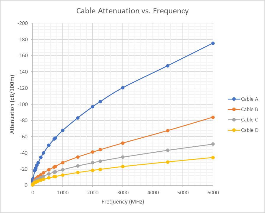
In the graph above, cable A is a thin and light cable with a diameter of only 2.5 mm; it presents the highest attenuation of the four. Cables B and C have the same external diameter of 7 mm but with different mechanical characteristics. Cable B is built to be flexible, targeting applications where cables are exposed to several bending cycles during operation. Cable C is a more regular cable used in fixed installations with limited bending cycles. Cable D is a thick and heavy cable with an external diameter of 10 mm; it globally offers low signal attenuation.
|
Cable Type |
Cable Diameter |
Mechanical Characteristic |
Attenuation (comparison) |
|---|---|---|---|
|
Cable A |
2.5 |
Rigid (single core) |
- - - - |
|
Cable B |
7 |
Flexible (stranded core) |
- - - |
|
Cable C |
7 |
Rigid (single core) |
- - |
|
Cable D |
10 |
Rigid (single core) |
- |
To obtain the maximum cable length that we can use in a system, we must know the maximum signal attenuation allowed by the system's receiver. For example, in a system where the signal attenuation allowed by the receiver is -17 dB at 3000 MHz, we can simply cross-multiply the known cable attenuation at the target frequency by the maximum allowed signal attenuation, which in this case is -17 dB. Computing the maximum cable length at 3000 MHz for Cables A, B, C, and D, we obtain the following:
|
Cable Type |
Cable Attenuation |
Target Frequency |
Max. Signal Attenuation |
Max. Cable Length |
|---|---|---|---|---|
|
Cable A |
-120 |
3000 |
-17 |
14.2 |
|
Cable B |
-52 |
32.7 |
||
|
Cable C |
-35 |
48.6 |
||
|
Cable D |
-23 |
73.9 |
As we can see in this example, the answer “It depends…” is still the right one. The signal attenuation along the cable strongly depends on several factors like the diameter of the coax core conductor, if it is made of a single rigid copper conductor or stranded for better flexibility, its quality, and the insulation materials. For a quick analysis purpose, we can say that thin and light cables have higher signal attenuation resulting in shorter cable reach, while thick and heavy cables have lower signal attenuation, thus longer cable reach. When cables have similar quality and diameter, the attenuation can vary in function of their mechanical characteristics:
| ● | more flexibility (stranded core) = more attenuation |
| ● | less flexibility (rigid core) = less attenuation |