
IOUT* Isolated Contact Output Ports
Applies to: ![]()
![]()
![]()
![]()
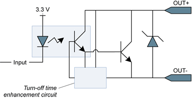
Isolated contact output (simplified schematic)
The isolated contact output ports have the following characteristics:
Galvanic isolation
| ● | each output is individually isolated |
| ● | isolation voltage: 500 VAC RMS |
DC specifications
| ● | Maximum open state voltage (measured across pins): +/- 30 V |
| ● | Maximum closed state current: 100 mA |
| ● | Maximum closed state voltage (measured across pins): |
| □ | 1 V at 100 mA |
| □ | 0.4 V at 1 mA (same as for LVTTL driver) |
| ● | Polarized output |
| ● | Remains in the OFF-state until the port is under control of the application |
| ● | The state of the port is reported through the OutputState MultiCam parameter. |
AC specifications
| ● | 5 µs (or better) turn-ON and turn-OFF time |
| ● | 100 kHz max frequency |
Typical switching performance at 25°C:
|
Current (mA) |
Turn-ON time delay (µs) |
Turn-OFF time delay (µs) |
|---|---|---|
|
0.5 |
2.0 |
4.8 |
|
1.0 |
2.0 |
3.9 |
|
4.0 |
2.2 |
3.3 |
|
10 |
2.3 |
2.7 |
|
40 |
2.3 |
2.7 |
|
100 |
2.3 |
2.7 |
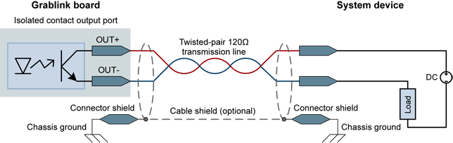
Any load within the 30 V / 100 mA envelope is accepted. The power originates from an external power source or alternatively from the power delivered through the 5V/12V and GND pins of the I/O connectors connector.
In this circuit, the current is supplied by the system device.
Notes
| ● | The isolated output is polarized. |
| ● | In case of polarity reversal, the output port acts as a closed contact. |
| ● | The isolated output is capable to deliver up to 100 mA and to switch voltages up to 30 V. |
| ● | Exceeding 100 mA or 30V may damage the output port. |
| ● | The +5V/+12V power may be delivered by the board. |