3610 HD26F I/O Extension Module - TTL-RS422 and
3612 HD26F I/O Extension Module - TTL-CMOS5V-RS422
Compatible with  1628 Grablink Duo, 3602 Coaxlink Octo, 3603 Coaxlink Quad CXP-12, 3603-4 Coaxlink Quad CXP-12, 3620 Coaxlink Quad CXP-12 JPEG, 3620-4 Coaxlink Quad CXP-12 JPEG, 3621 Coaxlink Mono CXP-12, 3621-LH Coaxlink Mono CXP-12 LH, 3622 Coaxlink Duo CXP-12, 3622-LH Coaxlink Duo CXP-12 LH, 3623 Coaxlink Quad CXP-12 Value and 3625 Coaxlink QSFP+.


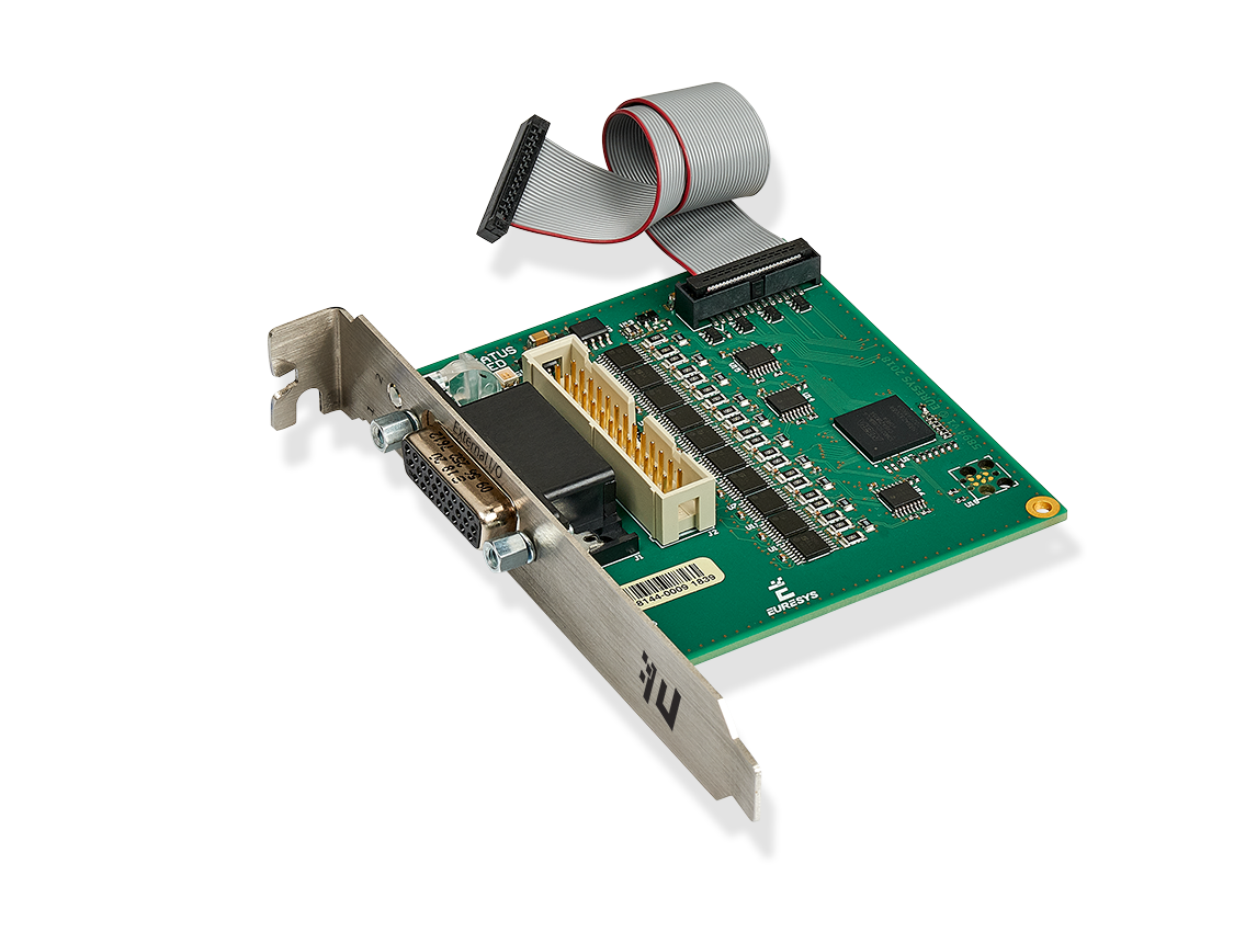
The 3610 HD26F I/O Extension Module - TTL-RS422 and the 3612 HD26F I/O Extension Module - TTL-CMOS5V-RS422 accessories are I/O extension modules to be used with frame grabber cards having an I/O extension connector.
These modules extend the I/O capabilities of the frame grabber with a configurable mix of 4 types of I/O ports:
|
□
|
single-ended 5 V compliant TTL input |
|
□
|
single-ended 3.3 V LVTTL (3610 only) or 5 V CMOS (3612 only) output |
|
□
|
differential RS-422 input |
|
□
|
differential RS-422 output |
The 3610 and the 3612 I/O extension modules are almost identical!
They differ only by the electrical specification of the single-ended outputs: low-voltage 3.3 V TTL for 3610, 5 V CMOS for 3612.
These modules:
|
□
|
are powered by the frame grabber through the I/O EXTENSION cable. |
|
□
|
are software configurable There are no jumpers. |
|
□
|
provide a persistent configuration. The last configuration is automatically restored at power-up |
Hot plugging is not allowed!
3610 HD26F I/O Extension Module - TTL-RS422

3612 HD26F I/O Extension Module - TTL-CMOS5V-RS422
|
□
|
Robust 26-pin high-density Sub-D |
|
□
|
Compatible pin layout with External I/O connectors of Coaxlink and Grablink Duo frame grabbers for 12 V/GND and signals pairs |
|
□
|
Standard pitch 26-pin flat cable header |
|
□
|
Compatible pin layout with Internal I/O connectors of Coaxlink and Grablink Duo frame grabbers for 12 V/GND and signals pairs |
|
●
|
I/O Extension connector |
|
□
|
Fine pitch 26-pin flat cable header fitted with the I/O Extension cable: a 150 mm length flat cable for direct connection to the I/O Extension connector of compatible frame grabbers |
Activity LED #1 on bracket
The ACTIVITY LED #1 is dedicated to the activity of input ports
| Green |
Normal mode - Flashing indicates activity on at least one input. |
| Orange |
Configuration mode |
| Red |
Error - The I/O module is not (yet) controlled by the frame grabber |
| Off |
The I/O module is not powered |
Activity LED #2 on bracket
The ACTIVITY LED #2 is dedicated to the activity of output ports
| Green |
Normal mode - Flashing indicates activity on at least one output. |
| Orange |
Configuration mode |
| Red |
Error - The I/O module is not (yet) controlled by the frame grabber |
| Off |
The I/O module is not powered |
Status LED on board
The STATUS LED is dedicated to the activity of the I/O extension bus
| Solid green |
Normal mode - No activity on the bus. |
| Flashing green |
Normal mode - Activity on the I/O extension bus. |
| Flashing orange |
Configuration mode - Activity on the I/O extension bus. |
| Flashing red |
Configuration mode - No activity on the I/O extension bus |
| Off |
The I/O module is not powered |
Electrical specifications
I/O configuration capabilities and constraints
| Group #1 |
MIO1 |
2 x TTL in |
2 x TTL out |
MIO1 |
4 x RS-422 in |
4 x RS-422 out |
| MIO2 |
| MIO3 |
2 x TTL in |
2 x TTL out |
MIO3 |
| MIO4 |
| MIO5 |
2 x TTL in |
2 x TTL out |
MIO5 |
| MIO6 |
| MIO7 |
2 x TTL in |
2 x TTL out |
MIO7 |
| MIO8 |
| Group #2 |
MIO9 |
2 x TTL in |
2 x TTL out |
MIO9 |
4 x RS-422 in |
4 x RS-422 out |
| MIO10 |
| MIO11 |
2 x TTL in |
2 x TTL out |
MIO11 |
| MIO12 |
| MIO13 |
2 x TTL in |
2 x TTL out |
MIO13 |
| MIO14 |
| MIO15 |
2 x TTL in |
2 x TTL out |
MIO15 |
| MIO16 |
| Group #3 |
MIO17 |
2 x TTL in |
2 x TTL out |
MIO17 |
4 x RS-422 in |
4 x RS-422 out |
| MIO18 |
| MIO19 |
2 x TTL in |
2 x TTL out |
MIO19 |
| MIO20 |
The 20 I/O ports are configurable by group. There are 3 groups:
|
□
|
The group #1 contains 8 single-ended I/O ports named MIO1 to MIO8 OR 4 differential I/O ports MIO1, MIO3, MIO5, MIO7. |
|
□
|
The group #2 contains 8 single-ended I/O ports named MIO9 to MIO16 OR 4 differential I/O ports MIO9, MIO11, MIO13, MIO15. |
|
□
|
The group #3 contains 4 single-ended I/O ports named MIO17 to MIO20 OR 2 differential I/O ports MIO17 and MIO19. |
Within a group, it is allowed to set all the I/O ports:
|
□
|
for differential input operation OR ... |
|
□
|
for differential output operationOR ... |
|
□
|
for single-ended operation. |
When the group is set for single-ended operation, it is allowed to set each pair of single-ended I/O:
|
□
|
for input operation OR ... |
The configuration is saved into a non-volatile memory on the I/O module. The configuration is automatically restored after applying power.
Software configuration
The IOExtensionModule category of the Interface module provides a set of features to configure the 3610/3612 I/O extension modules:
|
□
|
IOExtensionModuleConfiguration to enter/leave configuration mode |
|
□
|
IOExtensionModuleLineSelector to select a MIO to configure |
|
□
|
IOExtensionModuleLineFormat, IOExtensionModuleLineMode and IOExtensionModuleLineStatus to configure the selected MIO |
|
□
|
IOExtensionModuleLineToRepair and IOExtensionModuleErrorCount to help troubleshoot an invalid current configuration. |
Configuration procedure
|
1.
|
Select an Interface module |
|
2.
|
Enter the configuration mode: set IOExtensionModuleConfiguration to Begin |
|
3.
|
Select the I/O line to configure: set IOExtensionModuleLineSelector to the desired value (MIO1 to MIO20) |
|
4.
|
Select the single-ended or differential I/O line format |
|
□
|
For a single-ended I/O, set IOExtensionModuleLineFormat to TTL |
|
□
|
For a differential I/O, set IOExtensionModuleLineFormat to DIFF |
|
5.
|
Select the input or output I/O line mode: |
|
□
|
For an input, set IOExtensionModuleLineMode to Input |
|
□
|
For an output, set IOExtensionModuleLineMode to Output |
|
6.
|
Repeat from steps 3 for all I/O's to configure |
|
7.
|
Verify the validity of the configuration |
|
□
|
Get the value of IOExtensionModuleErrorCount |
|
□
|
If 0, the configuration is OK, proceed to next step |
|
□
|
If greater than 0, the configuration is NOK, proceed to step 10 |
|
8.
|
Record the configuration |
|
□
|
Set IOExtensionModuleConfiguration to Commit |
|
□
|
The procedure is complete! |
|
9.
|
Repair the configuration |
|
□
|
Get the value of IOExtensionModuleLineToRepair |
|
□
|
Adapt the configuration of one (or more) I/O's accordingly by proceeding from step 3 . |
GenApi Features
The IOExtensionModuleInformation category of the Interface module provides information details.
|
□
|
IOExtensionModuleSerialNumber
|
|
□
|
IOExtensionModulePartNumber
|
|
□
|
OExtensionModuleProductCode
|
|
□
|
IOExtensionModuleRevision |
|
□
|
IOExtensionModuleVariant
|
