
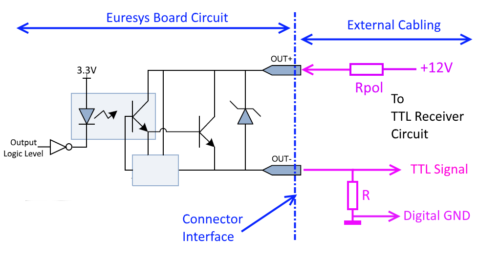
Using Local 12 V Power
The power supply voltage is taken from the I/O connector itself, using the power supply pin “+12V”.
This circuit needs two resistors, named R and RPOL.
A resistor of 180 ohm 1/8W is suggested for R, as best compromise but the circuit can also work within a large range of resistor values from 50 ohm 1/2W to 10K ohm 1/16 W (1).
A resistor of 560 ohm 1/4W is suggested for RPOL, as best companion of R = 180 ohm but the value of RPOLcan be adapted to match accordingly others R values.
If an existing pull-down resistor is already available at the TTL receiver side it can be used as R resistor to operate the circuit, avoiding the need of adding an extra resistor somewhere in the cabling.
The circuit does not perform logic level inversion.
Note: The resistor value can be also changed to match special static or dynamic performance requirements.
Note: The circuit does not perform logic level inversion.
Refer to Connectors for I/O connectors pin assignments.
| 1. | Connect OUT+ to +12V through a resistor (RPOL) of 560 ohm 1/4 W (or another resistor value that suits the circuit requirements). |
| 2. | Connect OUT- to the TTL input. |
| 3. | Pull-down OUT- with a resistor (R) of 180 ohm 1/8W (or another resistor value that suits the circuit requirements). |
The following table shows that the voltage levels are well compatible and that they remains acceptable voltage margins for both TTL and LVTTL applications.
Voltage levels and margins, Rpol = 560 ohm 1/4 W, R = 180 ohm 1/8W.
|
Isolated Output |
Isolated Output |
Isolated Output |
TTL Input |
Voltage Margin |
TTL Input |
|---|---|---|---|---|---|
|
High |
Close |
2.7 V max (2) |
2.0 V min |
0.7 V |
High |
|
Low |
Open |
0.36 V max (1) |
0.8 V max |
0.44 V |
Low |
Refer to Isolated Output for voltage levels of isolated outputs.
Note 1 0.36V is obtained considering a worst-case external (pull-up) load of 2 mA ( 180 ohm x 2 mA = 0.36V), which means that the circuit can support the presence of an external pull-up resistor up to a (minimum) value of 1K5 ohm (in 3.3V) or 2K4 ohm (in 5V). If needed, an other R value can be chosen according to the actual pull-up load within the circuit.
Note 2 RPOLlimits the Voh voltage to about 2.7V in order to match TTL and LVTTL levels.
2.7 V is obtained considering the RPOL-R 560 ohm-180 ohm divider and taking into account that the voltage drop across the opto-coupler pins (VOUT+ - VOUTt- ) is about 0.9V.
The maximum pulse width of isolated outputs is about 5 µs and the maximum pulse rate is 100 KHz,
Isolated outputs add an extra delay of about 5 µs in the signal propagation.
The resistor value of R = 180 ohm has good dynamic results for a usual capacitive loads as 1 or 2 meters of cable. As example, a 2m cable will add 100 pF of load (50pF/m) which give a rise time of about 18 µs at 180 ohm ( R x C = 180 ohm x 100 pF = 18 µs ) . If needed, the R value can be adapted to match special requirements in terms of rise time and/or capacitive load.
If maximizing the opto-coupler switching time is a concern, it is not recommended to not increase too much the value of the resistor. The opto-coupler circuit behaves better (switching times) with a load of about 10 mA or higher. R = 180 ohm loads the opto-coupler at 13 mA (3.3V) and 23 mA (5V).