Enable Signals Timing Diagrams
FVAL Timing for Area-Scan Acquisition
When the Grablink board is configured for image acquisition from area-scan cameras:
| ● | The rising edge of FVAL is used as a start of frame signal. |
| ● | The falling edge of FVAL is ignored. |
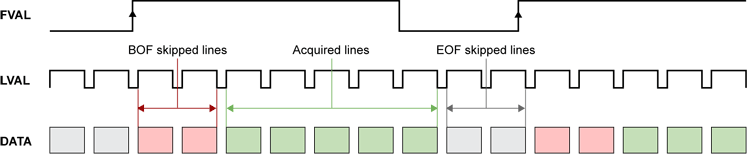
FVAL timing diagram (area-scan acquisition)
If the acquisition trigger is armed when FVAL raises, the board:
| 1. | Skips a pre-defined amount (VsyncAft_Ln) of video data lines at begin of frame (BOF), |
| 2. | Acquires a pre-defined amount (Vactive_Ln) of video data lines, |
| 3. | Terminates the image acquisition |
The subsequent video data lines are all skipped until a new FVAL rising edge occurs.
Applicable limits on FVAL timing for Area-Scan Acquisition
|
Parameter |
Min |
Typ |
Max |
Unit |
|---|---|---|---|---|
|
FVAL high duration |
64 |
Lines with active video |
N/A |
Clock cycle |
|
FVAL low duration |
64 |
Lines with blanked video |
N/A |
Clock cycle |
|
FVAL rising edge to LVAL rising edge setup time |
0 |
- |
N/A |
Clock cycle |
|
Skipped lines at begin of frame (BOF) |
0 |
0 |
255 |
LVAL cycle |
|
Skipped lines at end of frame (EOF) |
0 |
- |
N/A |
LVAL cycle |
Refer to Camera Active Area Properties for constraints on the value of Vactive_Ln.
FVAL Timing for Raw Data Acquisition
When the Grablink board is configured for raw data acquisition:
| ● | The rising edge of FVAL starts the data acquisition. |
| ● | The falling edge of FVAL stops the data acquisition. |
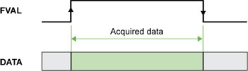
FVAL timing diagram (area-scan acquisition mode)
If the acquisition trigger is armed when FVAL rises, the board acquires all data until FVAL goes down.
You can configure the frame grabber to use the DVAL signal as a clock qualifier but this feature is rarely used. By default, the configuration ignores the DVAL signal. When DVAL is enabled, the data acquisition is inhibited for clock cycles where DVAL = 0.
Applicable limits on FVAL timing for Raw Data Acquisition
|
Parameter |
Min |
Typ |
Max |
Unit |
|---|---|---|---|---|
|
FVAL high duration |
1 |
- |
N/A |
Clock cycle |
|
FVAL low duration |
1 |
- |
N/A |
Clock cycle |
LVAL Timing Diagram
When the Grablink board is configured for image acquisition from an area-scan camera or from a line-scan camera:
| ● | The rising edge of LVAL is actually the reference for the horizontal timing |
| ● | The falling edge of LVAL is ignored |
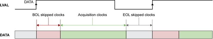
LVAL timing diagram
If, at the rising edge of LVAL, the acquisition of the next line is enabled, the board
| 1. | Skips a pre-defined amount (HsyncAft_Tk) of camera clock cycles at begin of line (BOL) |
| 2. | Acquires a pre-defined amount (Hactive_Px) pixel data |
| 3. | Terminates the line acquisition |
The subsequent clock cycles are skipped until a new LVAL rising edge occurs.
You can configure the frame grabber to use the DVAL signal as a clock qualifier but this feature is rarely used. Therefore, the default configuration ignores the DVAL signal.
Applicable limits on LVAL timing for Area-Scan and Line-Scan Acquisitions
|
Parameter |
Min |
Typ |
Max |
Unit |
|---|---|---|---|---|
|
LVAL high duration |
1 |
# clocks with active video |
N/A |
Qualified clock cycle |
|
LVAL low duration |
1 |
# clocks with blanked video |
N/A |
Qualified clock cycle |
|
Skipped clocks at begin of line (BOL) |
0 |
0 |
255 |
Qualified clock cycle |
|
Skipped clocks at end of line (EOL) |
0 |
- |
N/A |
Qualified clock cycle |
|
EOL skipped clocks |
Others: 0 |
- |
N/A |
Qualified clock cycle |
Refer to Camera Active Area Properties for constraints on the value of Hactive_Px.
A qualified clock cycle is defined as:
| ● | Any clock cycle when the frame grabber is configured to ignore DVAL. |
| ● | A clock cycle with DVAL = 1 when the frame grabber is configured to use DVAL. |
When DVAL is enabled:
| ● | The data acquisition is inhibited for clock cycles where DVAL = 0. Only the data corresponding to DVAL = 1 are effectively acquired. |
| ● | The BOL skipped clock counter is not incremented for clock cycles where DVAL = 0. In other words, HsyncAft_Tk specifies the amount number of "clock cycles with DVAL = 1" to skip at begin of line. |