I/O Ports Overview
Applies to: ![]()
![]()
![]()
![]()
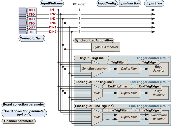
Every Channel owns a dedicated set of 10 system I/O ports including:
| ● | 4 isolated input ports named IIN1, IIN2, IIN3, IIN4 |
| ● | 2 high-speed differential input ports named DIN1, DIN2 |
| ● | 4 isolated output ports named IOUT1, IOUT2, IOUT3, IOUT4 |
|
Input Function |
DIN1 | DIN2 |
IIN1 |
IIN2 |
IIN3 |
IIN4 |
|---|---|---|---|---|---|---|
| General-Purpose Inputs | OK | OK | OK | OK | OK | OK |
| Trigger Input | OK | OK | OK | OK | OK | OK |
| End Trigger Input | OK | OK | OK | OK | OK | OK |
| Line Trigger Input | OK | OK | OK | OK | OK | OK |
| Isolated I/O SyncBus Receiver | - | - | - | - | OK | OK |
The input ports are individually designated by their I/O index. Refer to I/O Indices Catalog for a list of I/O indices for each product.
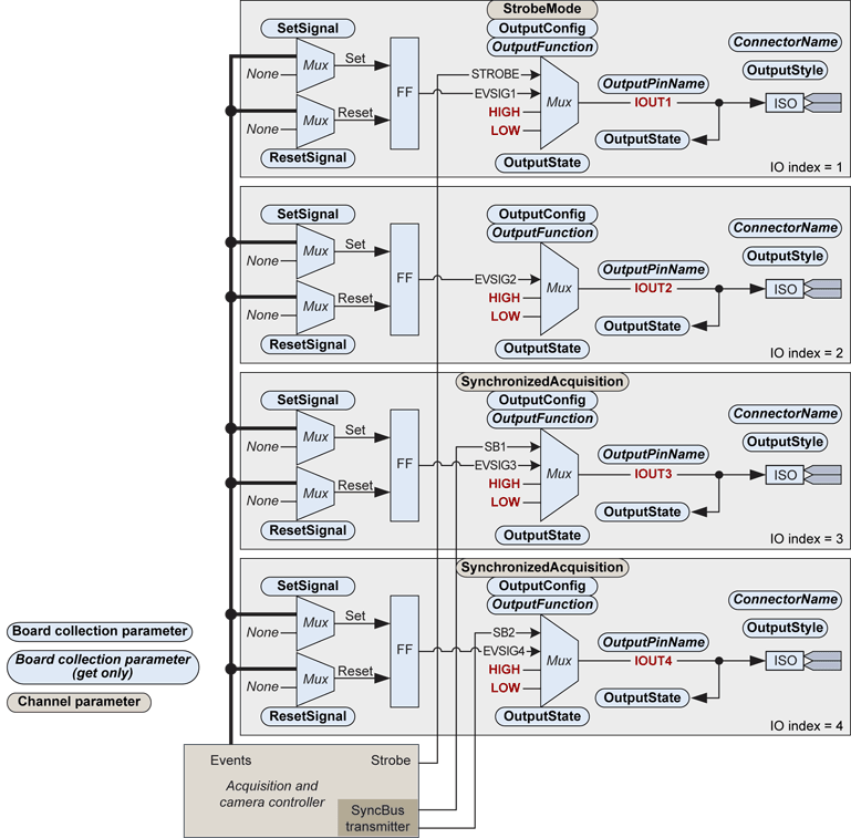
Organic diagram of the output ports of a set of system I/O
The four output ports are based on a uniform structure that includes the following elements:
A programmable event signal generator composed with a set/reset flip-flop and a pair of configurable multiplexers that selects the set and the reset conditions from a panel of internal "events" issued by the acquisition and camera controller.
An output multiplexer that selects the signal to be issued on the output port. Possible selections are :
| □ | "LOW" to connect any of the 4 output port to the logical level corresponding to the OFF state of the opto-coupler |
| □ | "HIGH" to connect any of the 4 output port logical level corresponding to the OFF state of the opto-coupler |
| □ | "EVSIGx" to connect any of the four output port to the signal issued by the respective event signal generator |
| □ | "STROBE" to connect the IOUT1 port to the signal produced by the acquisition and camera controller |
| □ | "SB1" to connect the IOUT3 port to the first of the two signals produced by the SyncBus transmitter of the acquisition and camera controller |
| □ | "SB2" to connect the IOUT4 port to the second of the two signals produced by the SyncBus transmitter of the acquisition and camera controller |
| ● | The ISO electrical interface built with an opto-coupler device. |
| ● | A readback circuit allowing getting at any time the actual logic state of the output multiplexer. |
|
Output Function |
IOUT1 |
IOUT2 |
IOUT3 |
IOUT4 |
LED | LED_A | LED_B |
|---|---|---|---|---|---|---|---|
|
OK |
OK |
OK |
OK |
- | - | - | |
|
OK |
OK |
OK |
OK |
- | - | - | |
|
OK |
- |
- |
- |
- | - | - | |
|
- |
- |
OK |
OK |
- | - | - | |
| Bracket LED Control | - | - | - | - | OK | OK | OK |
The output ports are primarily managed using Board class parameters belonging to the Input/Output Control Category :
OutputConfig is a set-only collection parameter that must be used by the application software to configure an output port for a particular usage.
OutputFunction is a get-only collection parameter that reports the actual function assigned to the output port designated.
The following state diagram shows the 3 states of OutputFunction and all the possible inter-state transition:
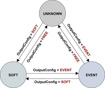
OutputFunction state diagram
The "UNKNOWN" state means that the function of the output port is not known by the MultiCam Board object. The output port is then free to be used by a MultiCam Channel for Strobe Output or Isolated I/O SyncBus Driver functions. Setting OutputConfig to FREE forces immediately OutputFunction to the value UNKNOWN. This is the default state after board startup.
The "SOFT" state means that the output port is directly under control of the application software for general-purpose usage. Setting OutputConfig to SOFT forces immediately OutputFunction to the value SOFT. The output port can be used by the MultiCam Board for General-Purpose Output function.
The "EVENT" state means that the output port is driven by the respective event signal generator for the event signaling usage. Setting OutputConfig to EVENT forces immediately OutputFunction to the value EVENT. The output port can be used by the MultiCam Board for Event Signaling function.
The output ports are individually designated by their I/O index. Refer to I/O Indices Catalog for a list of I/O indices for each product.