Hardware Trigger
When the frame grabber is configured for area-scan acquisition using the SNAPSHOT or the HFR acquisition modes, a (frame) trigger is an electrical signal sent by the external system to instruct the frame grabber to take control over the camera, including exposure control, and to perform a frame acquisition. This is usually used when an asynchronous capture of a moving object is involved. The trigger pulse is issued by a position sensor indicating when the observed object is adequately located in the field of view.
When the frame grabber is configured for line-scan acquisition using the WEB, PAGE or the LONGPAGE acquisition modes, a (page) trigger is an electrical signal sent by the external system to instruct the frame grabber to perform the acquisition of a set of several successive lines. This is usually used when a moving object is about to enter the field of view of the line-scan camera.
Each MultiCam channel elaborates a clean trigger event using a dedicated set of hardware resources including: source multiplexer, edge detector, noise filter, delay line and decimation filter.
The hardware trigger input function is available for a restricted set of AcquisitionMode, TrigMode and NextTrigMode acquisition control parameters. In the following table, a OK indicates that the hardware trigger input function is effectively used:
| Initial Trigger Event | Subsequent Trigger Events | ||||
|---|---|---|---|---|---|
|
TrigMode |
NextTrigMode |
||||
| HARD | SOFT | COMBINED | SAME | REPEAT | |
| IMMEDIATE | OK | - | OK | - | - |
| HARD | OK | OK | OK | OK | OK |
| SOFT | OK | - | OK | - | - |
| COMBINED | OK | OK | OK | OK | OK |
When hardware trigger is required, the following trigger control parameters need to be configured:
| Parameter | Value range |
|---|---|
| TrigCtl | See Source Selection and Electrical Style Control |
| TrigEdge | GOHIGH, GOLOW See Polarity Control |
| TrigFilter | See Filter Control |
| TrigDelay_us | See Delay Control |
| PageDelay_Ln | |
| TrigLine | See Source Selection and Electrical Style Control |
| TrigDelay_Pls | See Decimation Control |
| NextTrigDelay_Pls |
Applies to: ![]()
![]()
![]()
![]()
The trigger signal can originate from the following type of devices:
| 1. | An RS-422 compatible detector attached to any of the two high-speed differential input ports belonging to the channel or ... |
| 2. | ... another type of device attached to any of the 4 isolated current-sense input ports belonging to the channel. |
|
Sourcing device type |
TrigCtl |
Input Port |
TrigLine |
|---|---|---|---|
|
RS-422 |
DIFF | Diff. Input #1 | DIN1 |
| Diff. Input #2 | NOM or DIN2 | ||
|
Other detectors |
ISO | Isolated input #1 | IIN1 |
| Isolated input #2 | NOM or IIN2 | ||
| Isolated input #3 | IIN3 | ||
| Isolated input #4 | IIN4 |
To select a port:
| 1. | Set the value of the TrigCtl parameter corresponding to the electrical style of the sensor device used as trigger source. |
| 2. | Optionally, set the value of the TrigLine parameter corresponding to the I/O port used to attach the trigger detector. |
The default value of TrigLine is NOM.
The hardware trigger input ports are available on Internal IO and External IO connectors:
| Product |
Camera |
Connector(s) |
Trigger Input Ports |
|---|---|---|---|
|
|
- |
DIN1, DIN2 IIN1, IIN2, IIN3, IIN4 |
|
|
|
A | DIN1A, DIN2A IIN1A, IIN2A, IIN3A, IIN4A |
|
| DIN1A, DIN2A IIN1A, IIN2A |
|||
|
|
B | DIN1B, DIN2B IIN1B, IIN2B, IIN3B, IIN4B |
|
| DIN1B, DIN2B IIN1B, IIN2B |
|||
|
|
- | DIN1, DIN2 IIN1, IIN2, IIN3, IIN4 |
A trigger event is generated on a positive-going or a negative-going transition of the electrical signal.
To select the transition, set accordingly the value of the TrigEdge parameter:
|
TrigEdge |
Description |
|---|---|
|
GOHIGH |
The trigger event is generated at each positive-going transition of the trigger line |
|
GOLOW |
The trigger event is generated at each negative-going transition of the trigger line |
The default value for TrigEdge is GOHIGH.
The hardware signal flows through a digital filter that removes any pulse narrower than its time constant.
The filter strength is configurable in 3 steps by means of the TrigFilter parameter. Each step corresponds to a specific filter time constant.
| TrigFilter | Time Constant |
|---|---|
| OFF | 100 nanoseconds |
| ON or MEDIUM | 500 nanoseconds |
| STRONG | 2.5 microseconds (Default value) |
To avoid unexpected loss of trigger events, check that the selected time constant is shorter than the trigger pulse width sent by the detector!
Product specific notes
|
Product |
Description |
|---|---|
|
|
There is no digital filter for isolated inputs. |
For area-scan cameras operated with the SNAPSHOT or the HFR acquisition modes, the hardware frame trigger signal can be delayed by a user-programmable time delay.
For (TDI) line-scan cameras operated with the PAGE or the LONGPAGE acquisition modes, the hardware page trigger signal can be delayed by a user-programmable number of captured lines.
The following table shows the respective control parameters, their value range and the default value:
|
AcquisitionMode |
Parameter |
Value Range | Default Value |
|---|---|---|---|
| SNAPSHOT or HFR | TrigDelay_us | 0 to 2,000,000 (2 seconds) | 0 |
| PAGE or LONGPAGE | PageDelay_Ln | 0 to 65,534 lines | 0 |
The "number of captured lines" is equal to the "number of camera cycles" when the frame grabber is configured to capture all lines. When the frame grabber performs "downweb resampling", the "number of captured lines" might be different than the "number of camera cycles".
When the downweb line rate is linked to the web speed through an encoder, the delay expressed as a number of captured lines represents a fixed length on the web!
Applies to: ![]()
![]()
![]()
![]()
The trigger decimation feature applies:
| ● | when a hardware frame trigger source is selected for the area-scan SNAPSHOT or HFR acquisition modes. |
| ● | When a hardware page trigger source is selected for the (TDI) line-scan WEB, PAGE or LONGPAGE acquisition modes. |
Trigger decimation discards a configurable number of trigger events after the start of acquisition sequence and after every start of acquisition phase.
TrigDelay_Pls specifies the number of detected pulses on the hardware trigger line to be skipped after the acquisition sequence begins.
NextTrigDelay_Pls specifies the number of detected pulses on the hardware trigger or page trigger line to be skipped between successive acquisition phases.
|
Parameter |
Value Range | Default Value |
|---|---|---|
| TrigDelay_Pls | 0 to 65,536 pulses | 0 |
| NextTrigDelay_Pls | 0 to 65,536 pulses | 0 |
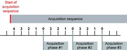
Acquisition rate and trigger decimation, with TrigDelay_Pls = 4 and NextTrigDelay_Pls = 3
NextTrigDelay_Pls is irrelevant for the LONGPAGE acquisition mode.