IOUT* Isolated Contact Output Ports
Applies to: ![]()
![]()
![]()
![]()
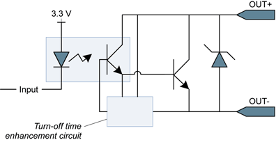
Isolated contact output (simplified schematic)
The output port implements an isolated contact output.
DC characteristics
| Parameter | Conditions | Min. | Typ. | Max. | Units |
|---|---|---|---|---|---|
| Current | 100 | mA | |||
| Differential voltage | Open state | -30 | 30 | V | |
| Closed state @ 1 mA | 0.4 | V | |||
| Closed state @ 100 mA | 1.0 | V |
| □ | The output port in the closed state has no current limiter, the user circuit must be designed to avoid excessive currents that could destroy the output port. |
| □ | The output port remains in the OFF-state until it is under control of the application. |
AC characteristics
| Parameter | Min. | Typ. | Max. | Units |
|---|---|---|---|---|
| Pulse rate | 0 | 100 | kHz | |
| Turn-on time | 5 | µs | ||
| Turn-off time | 5 | µs |
Typical switching performance @ 25°C
| Current [mA] | Turn ON time [µs] | Turn OFF time [µs] |
|---|---|---|
| 0.5 | 2.0 | 4.8 |
| 1.0 | 2.0 | 3.9 |
| 4.0 | 2.2 | 3.3 |
| 10 | 2.3 | 2.7 |
| 40 | 2.3 | 2.7 |
| 100 | 2.3 | 2.7 |
Isolation characteristics
| Parameter | Value |
|---|---|
| Isolation grade | Functional |
| Max. DC voltage | 250 V |
| Max. AC voltage | 170 VRMS |
The functional isolation is only for the circuit technical protection. It does not provide an isolation that can protect a human being from electrical shock!
Compatible loads
The following loads are compatible with the isolated contact output ports:
| ● | Any load within the 30 V / 100 mA envelope is accepted. The power originates from an external power source or alternatively from the power delivered through the 12 V and GND pins of the I/O connectors. |
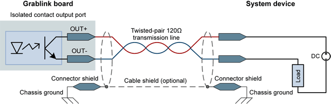
In this circuit, the current is supplied by the system device.
Notes
| ● | The isolated output is polarized. |
| ● | In case of polarity reversal, the output port acts as a closed contact. |
| ● | The isolated output is capable to deliver up to 100 mA and to switch voltages up to 30 V. |
| ● | Exceeding 100 mA or 30V may damage the output port. |
| ● | The +5V/+12V power may be delivered by the board. |