Quadrature Decoder
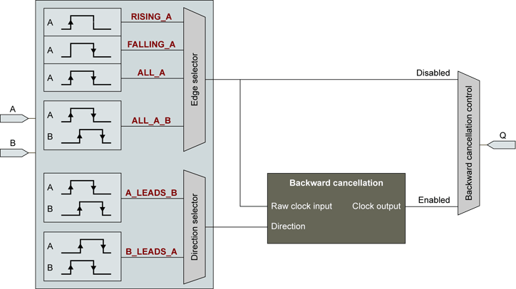
The quadrature decoder circuit interfaces directly with dual output phase quadrature incremental motion encoders. It decodes the encoder A and B signals and generates pulses on the Q output.

Quadrature decoder block diagram
Edge Selection
The rate of the output pulse can be 1, 2, or 4 times the frequency of the A signal according to the position of the edge selector.
- When the edge selector is in the rising A position, an output pulse is generated for every rising edge of the A signal. The falling edge on the A signal and both edges on the B-signal are ignored.
- When the edge selector is in the falling A position, an output pulse is generated for every falling edge of the A signal. The rising edge on the A signal and both edges on the B-signal are ignored.
- When the selector is in the All A position, an output pulse is generated for every rising and falling edges of the A signal. The B-signal is ignored.
- When the selector is in the All A B position, an output pulse is generated for every rising and falling edges of the A and B signals.
The edge selector is controlled by the enumerated MultiCam parameter LineTrigEdge.
Direction Selector
The motion direction is determined by the phase relationship of the A and B signals.
By construction, the dual-output phase quadrature incremental motion encoder maintains a phase relationship of about 90 degrees between the two signals. For motion in one direction, the A signal leads the B signal by about 90 degrees. For a motion in the other direction, the B signal leads the A signal by about 90 degrees.
The direction selector provides the capability to define which one of the phase relationships is considered as the forward direction for the application.
The default assignment identifies the case "A Leads B" as the forward direction.
Backward Motion Cancellation
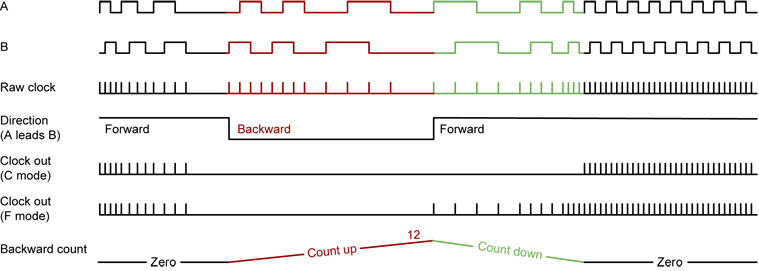
The backward cancellation circuit stops sending line trigger pulses as soon as a backward motion is detected. If such an event occurs, the acquisition is stopped.
When the backward cancellation control is configured in the filter mode (F-Mode), the line acquisition resumes when the motion changes to the forward direction. Therefore, the cancellation circuit filters out all the pulses corresponding to the backward direction.
When the backward cancellation control is configured in the compensation mode (C-Mode), the line acquisition resumes when the motion changes to the the forward direction at the place it was interrupted. Therefore, the cancellation circuit filters out not only the pulses corresponding to the backward direction, but a number of forward pulses equal to the number of skipped backward pulses.
In C-Mode, the cancellation circuit uses a "backward pulse counter" that:
- Increments by 1 every clock in the backward direction
- Decrements by 1 every clock in the forward direction until it reaches 0
- Resets at the beginning of each MultiCam acquisition sequence. More precisely, at the first trigger event of the sequence. This trigger is considered as the reference for the position along the web for the whole acquisition sequence.
In C-Mode, all pulses occurring when the counter value is different of zero are blocked.
The counter has a 16-bit span, backward displacement up to 65535 pulses can be compensated.

The backward cancellation circuit operates exclusively with quadrature motion encoders when LineRateMode = PULSE.
The backward cancellation mode is configured by BackwardMotionCancellationMode.


