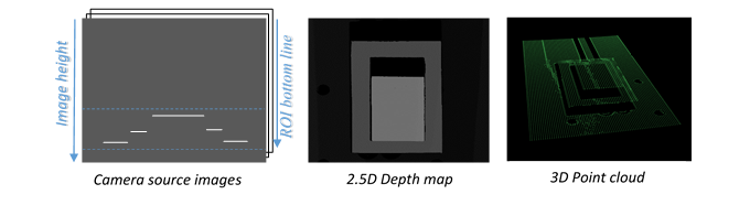
The calibration is used to apply the transformation between a depth map and a point cloud or a mesh.
There are 3 ways to set up this conversion:
| □ | Apply a simple scale on the pixel coordinates of the depth map (EScaleCalibrationModel class) |
| □ | Use the explicit geometric model (EExplicitGeometricCalibrationModel class) |
These models share the same base class ECalibrationModel and exposes the method Apply(), which is used to apply the conversion between a depth map pixel and a 3D point. It takes as input the coordinates of one point in a depth map and it returns the coordinates of the corresponding point in the 3D space.
The method Apply is not aware of the possible mirroring of the corresponding depth map and cannot make use of EDepthMap::AxisSystemType (see below). If necessary (when the corresponding depth map is vertically mirrored) the y coordinates should be flipped before calling the Apply method.
| □ | The class EDepthMapToPointCloudConverter generates a point cloud from a depth map, using one of the calibration models. |
| □ | The class EDepthMapToMeshConverter generates a mesh from a depth map, using one of the calibration models. |
By convention:
| □ | The origin of the referential is the lower-left corner of the depth map. |
| □ | The center of the first pixel at the lower-left corner is at x = 0.5 and y = 0.5. |
| □ | The center of the pixel at the upper-right corner is at x = width - 0.5 and y = height - 0.5 where width is the width of the depth map and height is its height. |
By default, Easy3D considers that the origin of the 3D axis of the depth map is the bottom left of the internal image buffer, and the Y axis is pointing up. This means that the depth map image is not seen as vertically mirrored compared to the real world image of the scanned object.
Nevertheless, depending on your acquisition setup this mirroring can happen (for example if the direction of the scan is inverted).
If this is your case, you can set the EDepthMap::SetAxisSystemType to EAxisSystem_UpperLeftCorner, meaning that the origin of the 3D axis is on the upper left corner and the Y axis is pointing down.
This value changes the behavior of the methods :
| □ | EObjectBasedCalibrationGenerator.Compute |
| □ | EDepthMapToPointCloudConverter.Convert |
| □ | EDepthMapToMeshConverter.Convert |
The scale model (EScaleCalibrationModel) only applies a simple factor on the X, Y and Z axis. These factors are the only parameters of EScaleCalibrationModel.
For depth maps coming from laser triangulation setup, this transformation does not produce corrected, metric points. It’s main use is to display depth maps as 3D data with the E3DViewer class.
The explicit geometric model (EExplicitGeometricCalibrationModel) defines a simple and ideal laser triangulation setup. The explicit calibration makes some strong assumptions on the setup geometry and can only be used when a minimum set of parameters are known:
| □ | The angles of the camera and the laser plane, in the counter clockwise direction. The camera angle must be positive. |
| □ | The height of the camera above the scanned object. |
| □ | The field of view of the camera defined by the sensor size (mm) and the optical focal length (mm). |
| □ | The physical distance between two line scans of the depth map (depends on acquisition rate and motion speed). |
| □ | The size of the image and the ROI origin used in laser line extraction (between the top (0) and the bottom (height) of the image). |
Use the "Easy3D_Setup_Configuration.xlsx" spreadsheet to compute and check your setup configuration and parameters.
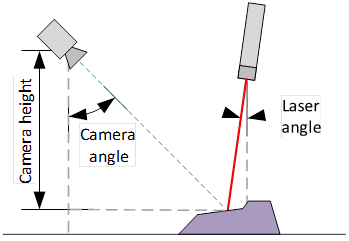
Explicit calibration setup with camera angle, laser angle and camera height
The setup of an explicit geometric calibration uses the constructor of the EExplicitGeometricCalibrationModel class.
Object-based calibration gives real world, metric, coordinates from an arbitrary laser triangulation setup. From the scan of a reference object, the calibration process tries to calculate all the parameters required for the transformation to the world space (position and attributes of the camera, position of the laser plane, relative motion of the object, optical distortion…).
For more details, please refer to the Object-Based Calibration Guidelines section.