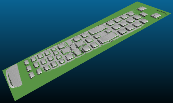
This topic presents a complete 3D processing workflow, featuring a TV remote controller as sample object.
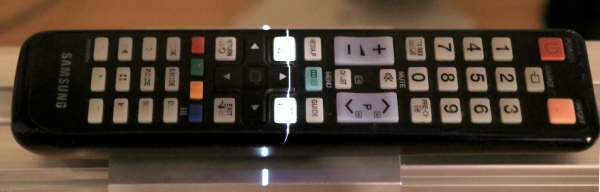
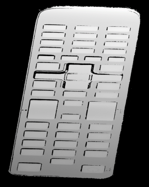
The remote controller on the laser triangulation acquisition setup

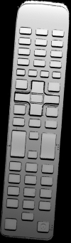
The remote controller after 3D processing and projection on a 2D image
The proposed process is the sequence of the following operations:
One time calibration process:
| 1. | Load a depth map representing the calibration object. |
| 2. | Perform the calibration model computation. |
| 3. | Store the calibration model. |
For each object:
| 1. | Load the object depth map. |
| 2. | Apply the calibration model to get the world point cloud. |
| 3. | (Optional) Save the point cloud to a PCD file. |
| 4. | Search for a reference plane by either: |
| □ | Choosing 3 points on the remote depth map to be used to compute a plane. |
| □ | Using the 3DPlaneFitter function. |
| 5. | Choose 2 points to define an orientation. |
| 6. | Build a ZMap using the reference plane and the orientation vector. |
| 7. | (Optional) Save the ZMap as an image. |
| 8. | Query the ZMap to get world space measurement. |
| 9. | Process the ZMap with 2D image function. |
For easier reading, the code snippets in this example do not show exception catching and error checking.
The calibration process is mandatory to find the exact transformation from the depth map to the real world, metric, coordinate system.
Open eVision features an object based calibration process: the scan of a reference object of known geometry is used in the calibration calculation.
The recommended calibration object is the double truncated pyramid.
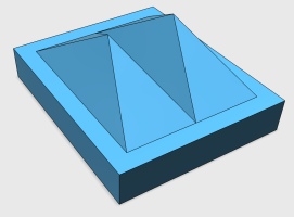
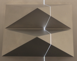
CAD model of the double pyramid and calibration object scanned
Using a Euresys Coaxlink 3D LLE frame grabber, the captured image is directly a depth map. Depth maps are 8 bits or 16 bits grayscale images with the pixel values representing the height of the laser profile.
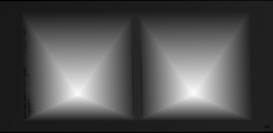
A depth map (gray scale image) of a double pyramid, used as the calibration object
The code snippet below shows how to load the depth map representing the double pyramid object, using it to compute a calibration model and save the result for later use.
  // Load the depthmap used for the calibration process
  EDepthMap16 calibration_depthmap;
  calibration_depthmap.Load("calibration.tiff");
  // Set the Z resolution from the number of bits for the fractional part, depends on the depth map acquisition
  calibration_depthmap.SetZResolution(1.f / (1<<5));

  // Declare the object based calibration generator
  EObjectBasedCalibrationGenerator calibrator;
  // set the real world scale of the scanned object
  calibrator.SetCalibrationObjectType(EObjectBasedCalibrationType_DoublePyramid);
  calibrator.SetCalibrationObjectScale(10.f);

  // Declare an object based calibration model
  EObjectBasedCalibrationModel calibration_model;

  // Perform the calibration process (can take some time, like 10 seconds)
  calibration_model = calibrator.Compute(calibration_depthmap);

  // Check the calibration result
  if(calibration_model.IsInitialized())
    {
       printf("Calibration succeeded with score: %g\n", calibration_model.GetCalibrationError());
       // Save the model for later use
       EFileSerializer serializer(ESerializerMode_Write, "calibration.model");
       calibration_model.Save(&serializer);
    }
    else
    {
       printf("Calibration failed\n");
    }
This section exposes the 3D workflow, from the source depth map to metric measurement.
The calibration model previously calculated is used to transform the depth map data to real world 3D point cloud.
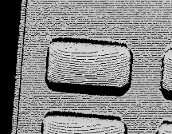
A depth map of the TV remote controller
(the object is distorted and scaled while black pixels represent undefined regions, that is parts of the object that were not seen by the camera or lit by the laser)
The code snippet below:
| 10. | Loads a calibration model. |
| 11. | Transforms the depth map to a 3D point cloud. |
| 12. | Saves the point cloud to a PCD file. |
  // Read an abstract calibration model from file
  EFileSerializer serializer(ESerializerMode_Read, "calibration.model");
  std::unique_ptr<ECalibrationModel> calibration_model = ECalibrationModel::Create(&serializer);

  // Declare a depth map to point cloud converter
  EDepthMapToPointCloudConverter dm2pc;
  // attach a calibration model to the converter
  dm2pc.SetCalibrationModel(*calibration_model);

  // Generate the point cloud
  EPointCloud point_cloud;
  dm2pc.Convert(object_depthmap, point_cloud);

  printf("Point cloud size : %d\n", point_cloud.GetNumPoints());

  // Save to point cloud to a PCD file
  point_cloud.SavePCD("point_cloud.pcd");
The PCD file is a simple 3D point container, used by the PCL framework (www.pointclouds.org). Such file can be loaded in the PCL viewer of other tools like Cloud Compare (www.cloudcompare.org).
As shown on the screen shots below, data in point cloud are in world coordinate system, expressed in the calibration object units. Distances and angles are correct and then metric measures are possible. However, processing on point clouds can be difficult and costly and then the ZMap representation is an alternative allowing 2D processing on metric world space.
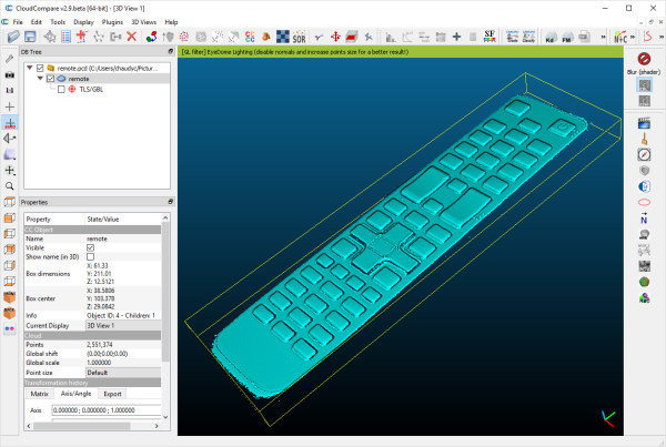
The resulting point cloud viewed in the Cloud Compare application
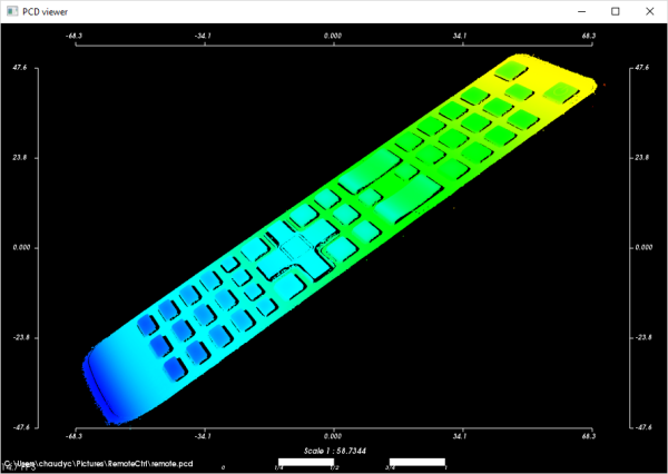
The resulting point cloud in the PCL viewer; the color ramp shows that the main body plane of the remote is not aligned with an axis
To perform measurements and processing, it is usually mandatory to transform the data to a reference frame. For the remote controller, we want to level to the main plane supporting the keys and orient the points along the remote edge.
If the depth map has been previously registered (by a consistent acquisition process or by the detection of fiducial markers), it may be possible to build the reference plane from 3 chosen points (points to be known as part of the reference plane).
  // Use 3 known points to build the reference plane
  E3DPoint p1(600.5, 450.5, object_depthmap.GetZValue(600, 450));
  E3DPoint p2(1700.5, 470.5, object_depthmap.GetZValue(1700, 470));
  E3DPoint p3(840.5, 2300.5, object_depthmap.GetZValue(840, 2300));

  // convert these points from depth map space to world space, using the calibration model
  E3DPoint w1, w2, w3;
  w1 = calibration_model.Apply(p1);
  w2 = calibration_model.Apply(p2);
  w3 = calibration_model.Apply(p3);

  // build the world plane using 3 points
  E3DPlane reference_plane(w1, w2, w3);
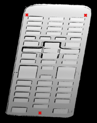
The original object depth map and the position of 3 points used for the reference plane calculation
Another option, if the depth map is not registered, is to use the E3DPlaneFitter class. This function tries to find the main plane from a point cloud using a probabilistic approach. It finds a subset of the point cloud that lies on a plane, given a user defined threshold tolerance.
The distance tolerance is a parameter of E3DPlaneFitter and must be adapted depending on the scale, noise and curvature of the plane in the point cloud.
  // Use a E3DPlaneFinder with a distance tolerance of 0.1 (world space coordinate)
  float distance_tolerance=0.1f;
  EPlaneFinder plane_finder(distance_tolerance);
  E3DPlane reference_plane=plane_finder.Find(point_cloud);
The principal plane (in green) extracted from the point cloud by E3DPlaneFinder class
The ZMap is a gray scale 2D image, representing the projection of the 3D points to a reference plane. The value of the pixels of the ZMap is the distance of the 3D point to the reference plane, coded in a fixed point representation.
The ZMap also supports the “undefined pixel” specific value, when no point is projected on a pixel and there is no valid value at that position.
As shown below, the point cloud to ZMap conversion can be made using default values for all parameters: resolution and scale of the ZMap, reference plane, orientation, origin will all be chosen automatically.
  // Create the converter
  EPointCloudToZMapConverter pc2zmap;

  // Create a 16 bits ZMap and fill it with point cloud points
  EZMap16 zmap;
  pc2zmap.Convert(point_cloud, zmap);

  // Save the ZMap as a PNG image
  zmap.SaveImage("zmap.png");
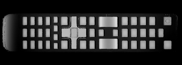
The generated depth map with default parameters
The body of the remote is not leveled and the object is not aligned. Nevertheless, comparing to the depth map, the ZMap is a calibrated representation of the object. Metric distances can be evaluated on the ZMap.
The current implementation of the ZMap converter simply projects 3D points on the ZMap image. Thus, depending on the point density and projection parameters, undefined pixels and region may appear in the ZMap.
The ZMap converter automatically perform a filling algorithm on undefined pixels. Disable it with the EnableFillMode(false).
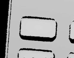
EnableFillMode(false) and EnableFillMode(true)
To avoid undefined pixels, choose a target scale for the ZMap. The method SetScale() changes the target X and Y resolution (in metric unit per pixel).
With the default configuration, the ZMap generator uses a horizontal reference plane. Use the SetReferencePlane() method to “level” the object and use the main body as the reference plane. SetOrientationVector() specifies the direction of the X (width) axis of the ZMap. The orientation vector allow to “rotate” the object around the reference plane normal.
  // level the object by defining a reference plane
  pc2zmap.SetReferencePlane(reference_plane);

  // align to the world Y axis
  pc2zmap.SetOrientationVector(E3DPoint(-0.07501, 0.9964, -0.03761));

  // choose a resolution of 0.2mm per pixel
  pc2zmap.SetMapXYResolution(0.2f);

  // generate the ZMap
  pc2zmap.Convert(point_cloud, zmap);
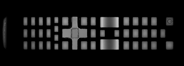
The ZMap with a reference plane previously calculated, an orientation to align the object and a reduced resolution
Use queries on ZMap to retrieve metric coordinates (for example, to measure the size and/or the height of a feature). Useful functions are GetWorldPositionFromPixelPosition(x,y) and GetZValue(x,y).
  float h1 = zmap.GetZValue(638, 128);       // get “height” at position P1
  float h2 = zmap.GetZValue(595, 128);       // get “height” at position P2

  E3DPoint p3 = zmap.GetWorldPositionFromPixelPosition(437, 98);  // get world position at p3
  E3DPoint p4 = zmap.GetWorldPositionFromPixelPosition(437, 288); // get world position at p4
  float d = p3.DistanceTo(p4);                     // world distance between p3 and p4
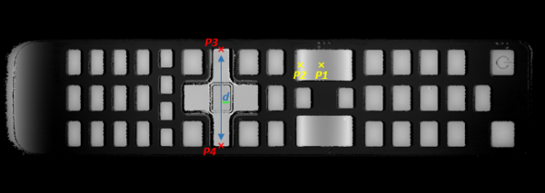
| ● | h1 (1.15601) and h2 (1.83618) are distance above the ZMap reference plane. These are values in millimeters, the difference evaluates the “curvature” of the key. |
| ● | P1 (58.843, 84.7838, 32.1084) and P2 (20.9479,81.9271, 32.0041) are positions in the original 3D world space. |
| ● | The distance d (38.0028) represents the width of the remote keyboard in millimeters. |
The reference plane can be shifted (translated) to remove the remote controller body and keep only the keys in the ZMap. An 8 bits ZMap must be used to be compatible the other Open eVision 2D libraries.
  // shift the plane by 1mm in the normal direction
  float d = reference_plane.GetSignedDistanceFromOrigin();
  reference_plane.SetSignedDistanceFromOrigin(d + 1.f);
  pc2zmap.SetReferencePlane(reference_plane);
  // choose the scale for the Z axis (2mm for 256 grey scale values)
  pc2zmap.SetMapZResolution(2.f / 256);
  // convert the point cloud to a 8 bits ZMap
  EZMap8 zmap8;
  pc2zmap.Convert(point_cloud, zmap8);
ZMap with shifted reference plane: only the keys remain visible while other pixels are set to 0 (undefined value)
This image can be used in 2D libraries like EasyImage, EasyObject or EasyGauge.
On a ZMap, the gray value of a pixel is the distance (height) above the reference plane. Threshold, filters, morphology and other image operators can be used directly.
Here is an example of a region segmentation using EasyObject:
  // segment the objects of the ZMap (default is Minimum Residue segmentation method)
  ECodedImage2 coded_image;
  EImageEncoder image_encoder;
  image_encoder.Encode(zmap8.AsEImage(), coded_image);

  // filter the object by area
  EObjectSelection object_selection;
  object_selection.AddObjects(coded_image);
  object_selection.RemoveUsingUnsignedIntegerFeature(EFeature_Area, 100, ESingleThresholdMode_Less);
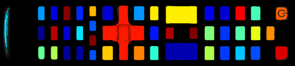
The extracted objects with EasyObject on the ZMap image
The ZMap includes a EWorldShape object that you can use for EasyGauge measurement. The EWorldShape class represents the scale between the image space and the world space.
  // get the world shape from the ZMap
  const EWorldShape& world_shape = zmap8.GetWorldShape();

  // setup a point gauge using that world shape
  EPointGauge pointGauge;
  pointGauge.Attach(&world_shape);

  // set gauge center point and tolerances in world space (mm)
  pointGauge.SetCenterXY(128.f, 25.f);  // 128mm and 25mm from the upper left corner
  pointGauge.SetTolerances(15.f, 0.f);  // 15mm, half gauge size

  // perform the measurement on the ZMap
  pointGauge.Measure(&zmap8.AsEImage());

  // get the 2 points and calculate the length of the key, values are in millimeters
  EPoint p1 = pointGauge.GetMeasuredPoint(0);
  EPoint p2 = pointGauge.GetMeasuredPoint(1);
  float length = p1.Distance(p2);	// return 21.619mm
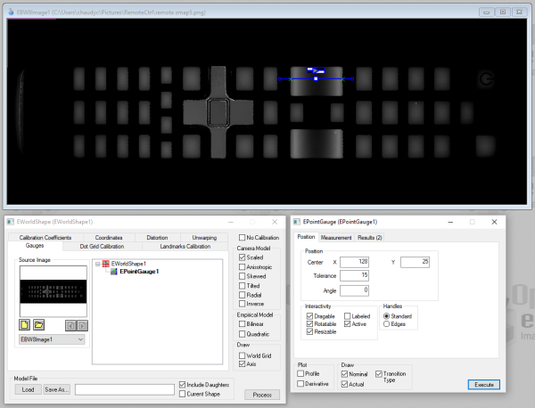
A point gauge on a ZMap in Open eVision Studio: the parameters are the same as the code snippet above